
Dilating fan duct nozzle

a technology of dilating nozzles and nozzles, which is applied in the direction of marine propulsion, vessel construction, aircraft navigation control, etc., can solve the problems of prior art nozzles that are problematic and suffer from various undesirable limitations, prior art nozzles that are insufficient to minimize the noise of gas turbine engines, and prior art turbofan engines are problemati

Active Publication Date: 2010-01-28
SPIRIT AEROSYSTEMS
View PDF22 Cites 30 Cited by
  • Summary
  • Abstract
  • Description
  • Claims
  • Application Information

AI Technical Summary

Problems solved by technology

Prior art exhaust nozzles are problematic and suffer from various undesirable limitations.
For instance, prior art nozzles are insufficient at minimizing noise from gas turbine engines.
Also, prior art turbofan engines are problematic because the bypass fan discharges air through a bypass duct and thereby generates significant noise.
Prior art turbofan bypass ducts fail to adequately reduce turbofan noise and optimize propulsion performance.

Method used


Image

  • Dilating fan duct nozzle
  • Dilating fan duct nozzle
  • Dilating fan duct nozzle

Examples


Embodiment Construction

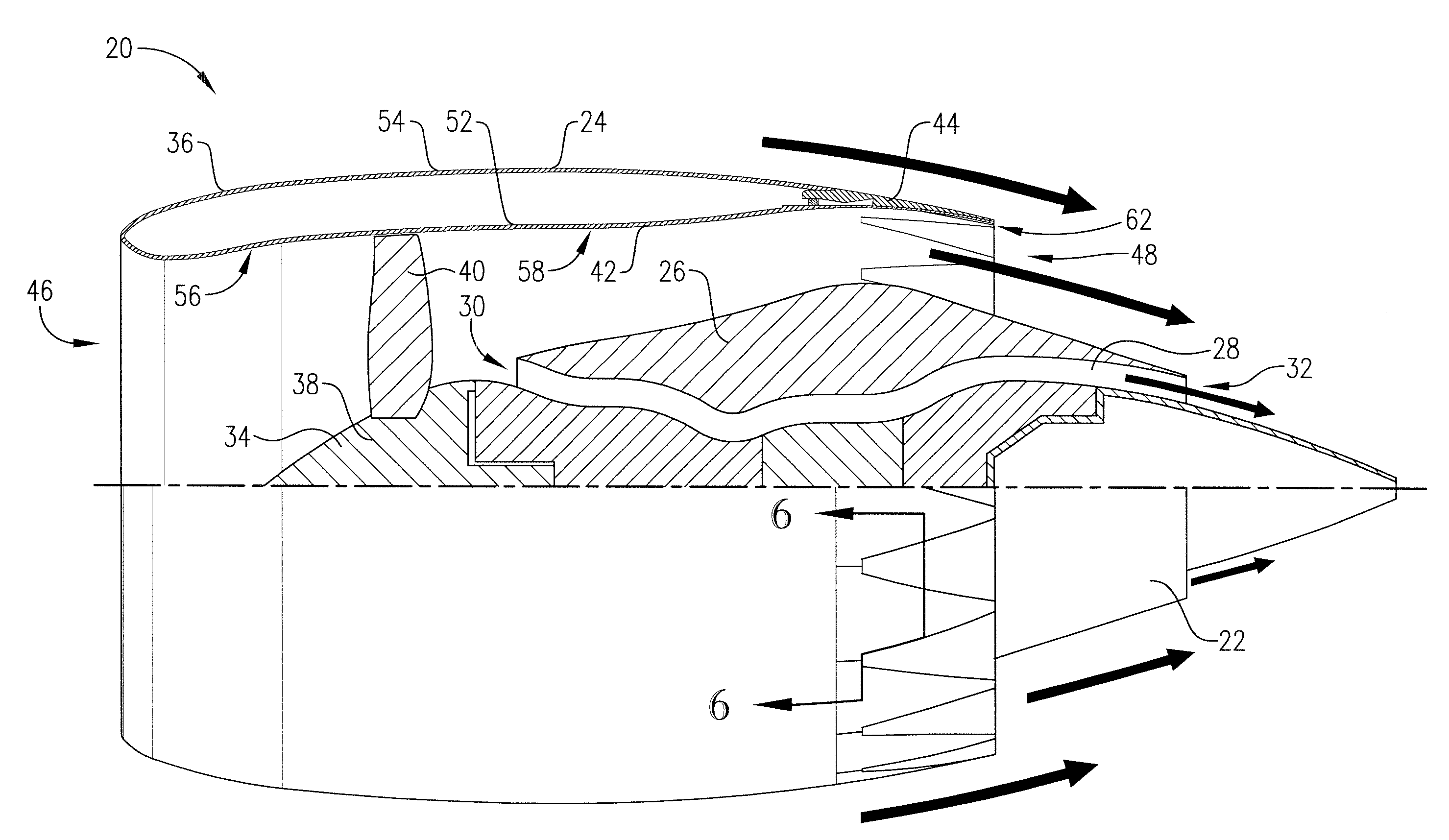
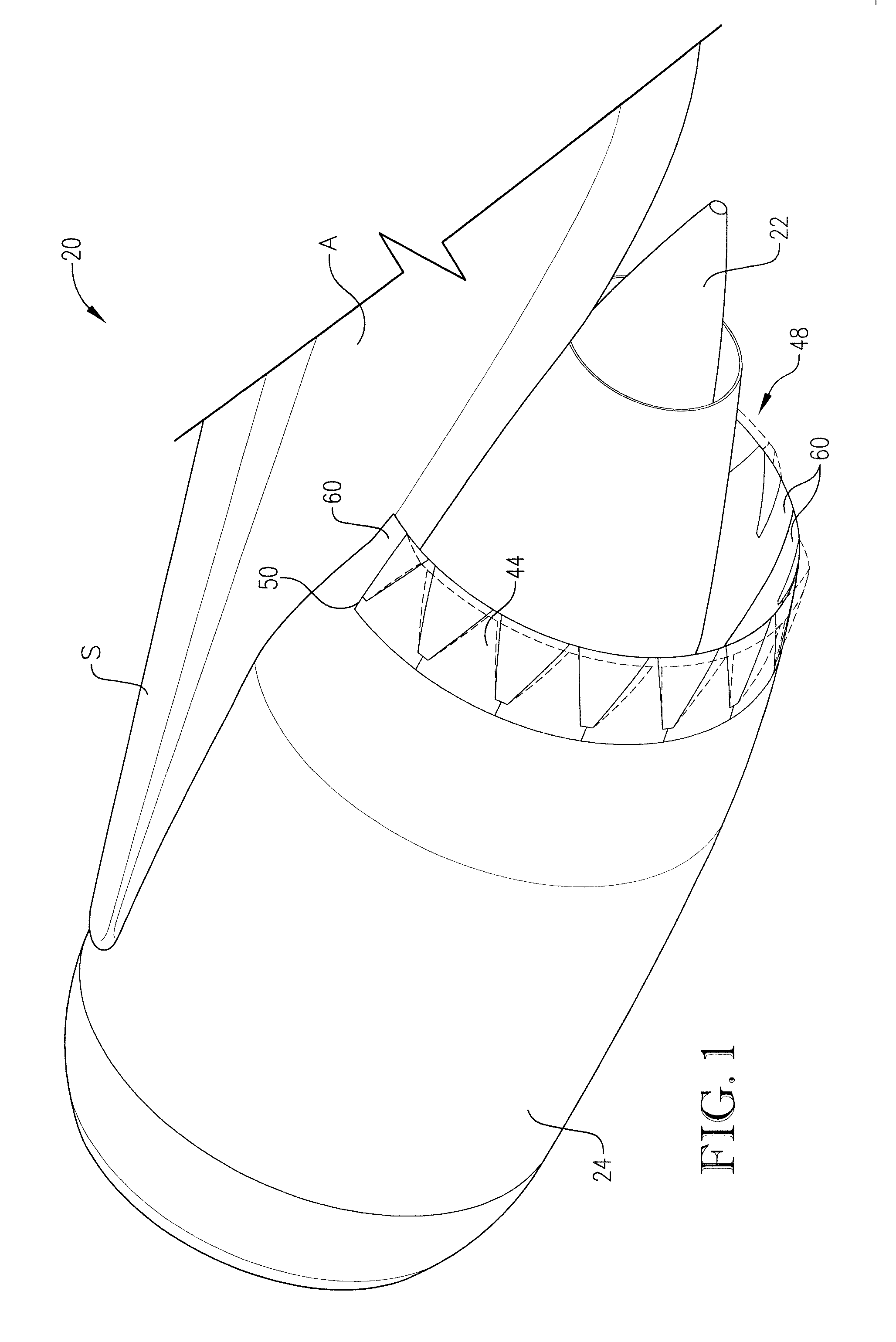
[0030]Turning initially to FIG. 1, a turbofan engine 20 is illustrated. A turbofan engine is a gas turbine engine that is operable to provide thrust for a jet aircraft A. Although the illustrated turbofan engine 20 is preferred, the principles of the present invention are applicable where other types of gas turbine engines, e.g., turbojet or turboprop, are used. The turbofan engine 20 broadly includes an engine core 22 and a ducted fan assembly 24.

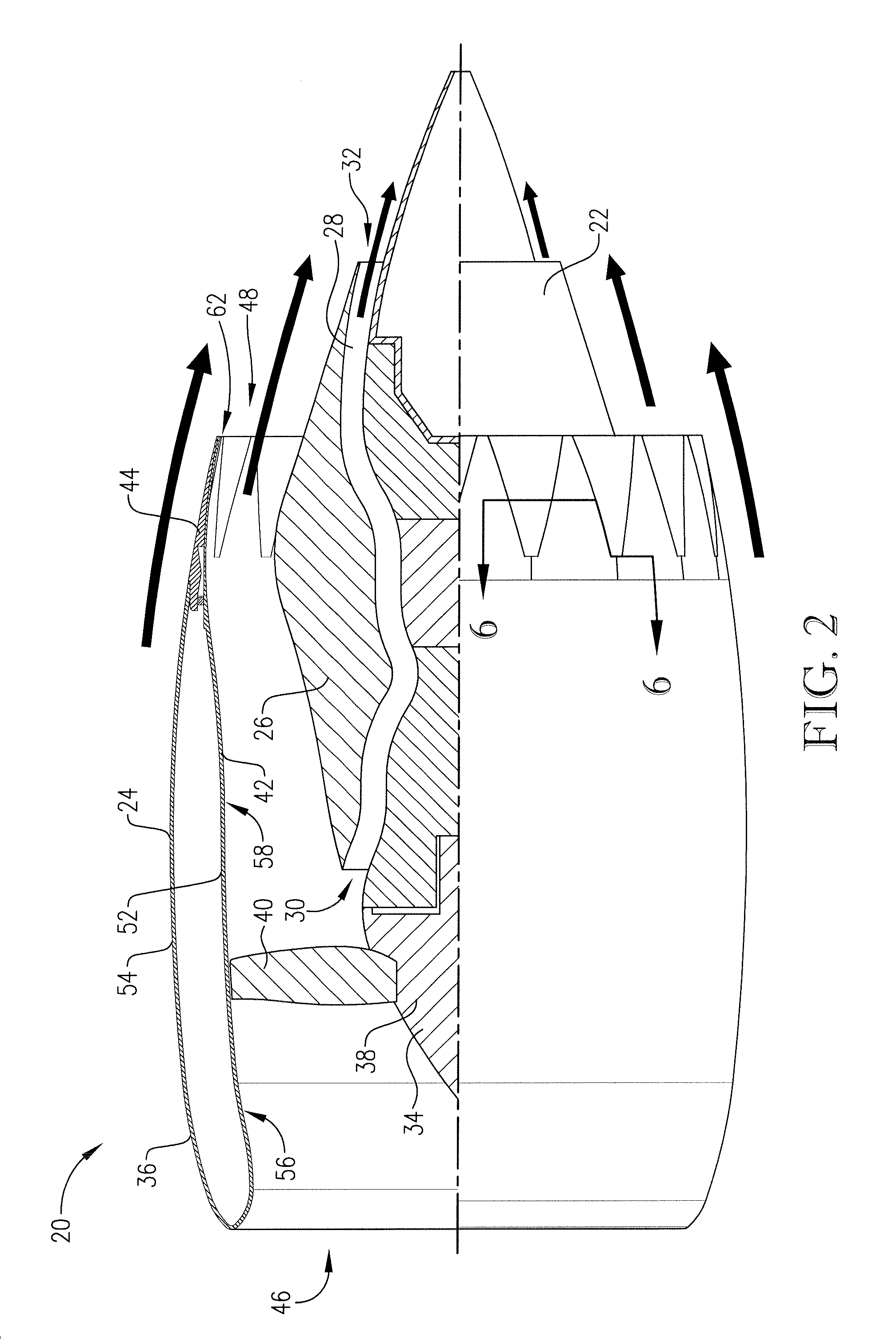
[0031]Turning to FIGS. 1-3, the engine core 22 is coupled to a strut S of the jet aircraft A and operates in a manner similar to a turbojet. However, the engine core 22 serves to power the ducted fan assembly 24, as will be discussed in greater detail. The engine core 22 includes a housing 26 that partly defines a flow path 28. In the usual manner, the engine core 22 also includes a compressor (not shown), a combustion assembly (not shown), and a turbine (not shown) that are spaced along the flow path 28. Thus, ambient air is drawn into an...


PUM


Abstract

A turbofan engine includes an engine core and a ducted fan assembly, with the ducted fan assembly including an annular cowling and a dilating fan duct nozzle. The nozzle includes continuous nozzle sections with intermeshing tiles. The tiles include drive tiles that are pivotal between nominal and dilated positions and driven tiles that intermesh with the drive tiles and shift with the drive tiles between the positions. The intermeshing tiles cooperatively adjust an orifice size of the nozzle by shifting between the positions and thereby affect the thrust and noise developed by the ducted fan assembly.

Description

BACKGROUND[0001]1. Field[0002]The present invention relates generally to nozzles for directing gas flow. More specifically, embodiments of the present invention concern a dilating nozzle for directing gas flow out of a jet engine.[0003]2. Discussion of Prior Art[0004]Conventional jet engines include a housing that directs air around the housing, directs air into the engine, and directs exhaust gas out of the engine. The housing normally includes an exhaust nozzle that defines an exit area of the engine and thereby affects the exhaust flow velocity out of the engine. Variable area exhaust nozzles are also known in the art and are operable to adjust the exhaust flow velocity and thereby change the engine thrust. Also, turbofan jet engines are known in the art and include a bypass fan that develops thrust.[0005]Prior art exhaust nozzles are problematic and suffer from various undesirable limitations. For instance, prior art nozzles are insufficient at minimizing noise from gas turbine ...

Claims


Application Information

Patent Timeline
IPC IPC(8): F02K1/06
CPCB64D33/06F05D2300/505F02K3/075F02K1/1207
Inventor CORE, ROBERT ARTHUR
Owner SPIRIT AEROSYSTEMS
Learn More