Coriolis effect mass flow meter and gyroscope
a mass flow meter and coriolis effect technology, applied in the field of mass flow meter, can solve the problems of unsatisfactory all-in-one, poorly suited to use across broad varying temperature ranges, and poorly suited to individual injector nozzle application, so as to and minimize unwanted disk motion and vibration
- Summary
- Abstract
- Description
- Claims
- Application Information
AI Technical Summary
Benefits of technology
Problems solved by technology
Method used
Image

Examples
Embodiment Construction
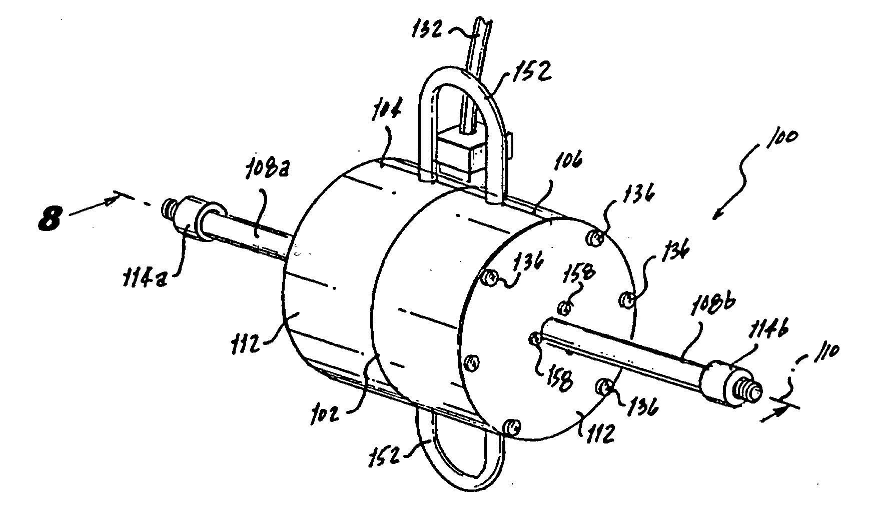
[0050]Referring now to the drawings, there is illustrated in FIG. 1 a perspective view of a mass flow meter in accordance with the subject invention and referred to generally by the reference numeral 100. In overview, the flow meter 100 measures the mass of the fluid passing there through by using the Coriolis effect. Many if not all the features of the flow meter 100 are symmetrical across a midpoint 102 between a leading half 104 and a trailing half 106 of a housing 112. The following description is more detailed with respect to the leading half 104 of the flow meter 100. Like reference numerals are used on the trailing half 106 to identify or otherwise refer to similar structural features or elements but with the letter “b” appended thereto rather than the letter “a” as used in the leading half 104.
[0051]The flow meter 100 is connected inline with the fuel fluid path so that the fuel flow enters an inlet tube 108a, which is substantially along a central axis 110, and exits an out...
PUM
 Abstract
Description
Claims
Application Information
PatSnap Eureka turns technology decisions into work you can execute. Powered by our Innovation Knowledge Graph, it runs expert workflows across engineering, life sciences, materials and intellectual property. Get your review-ready output in minutes.


