Valvetrain oil control system and oil control valve

a technology of oil control system and valvetrain, which is applied in the direction of non-mechanical valves, fluid pressure control, instruments, etc., can solve the problems of similar effects on the oil flow rate of all system components, and achieve the effect of reducing the oil consumption of the engine valve-train

Inactive Publication Date: 2010-01-28
EATON CORP
View PDF14 Cites 80 Cited by
  • Summary
  • Abstract
  • Description
  • Claims
  • Application Information

AI Technical Summary

Benefits of technology

[0006]A hydraulic control system is provided for reducing oil consumption of an engine valve-train. The hydraulic control system inclu...

Problems solved by technology

Additionally, as the flow rate and pressures within the system changes due to temperature and en...

Method used


Image

  • Valvetrain oil control system and oil control valve
  • Valvetrain oil control system and oil control valve
  • Valvetrain oil control system and oil control valve

Examples


Embodiment Construction

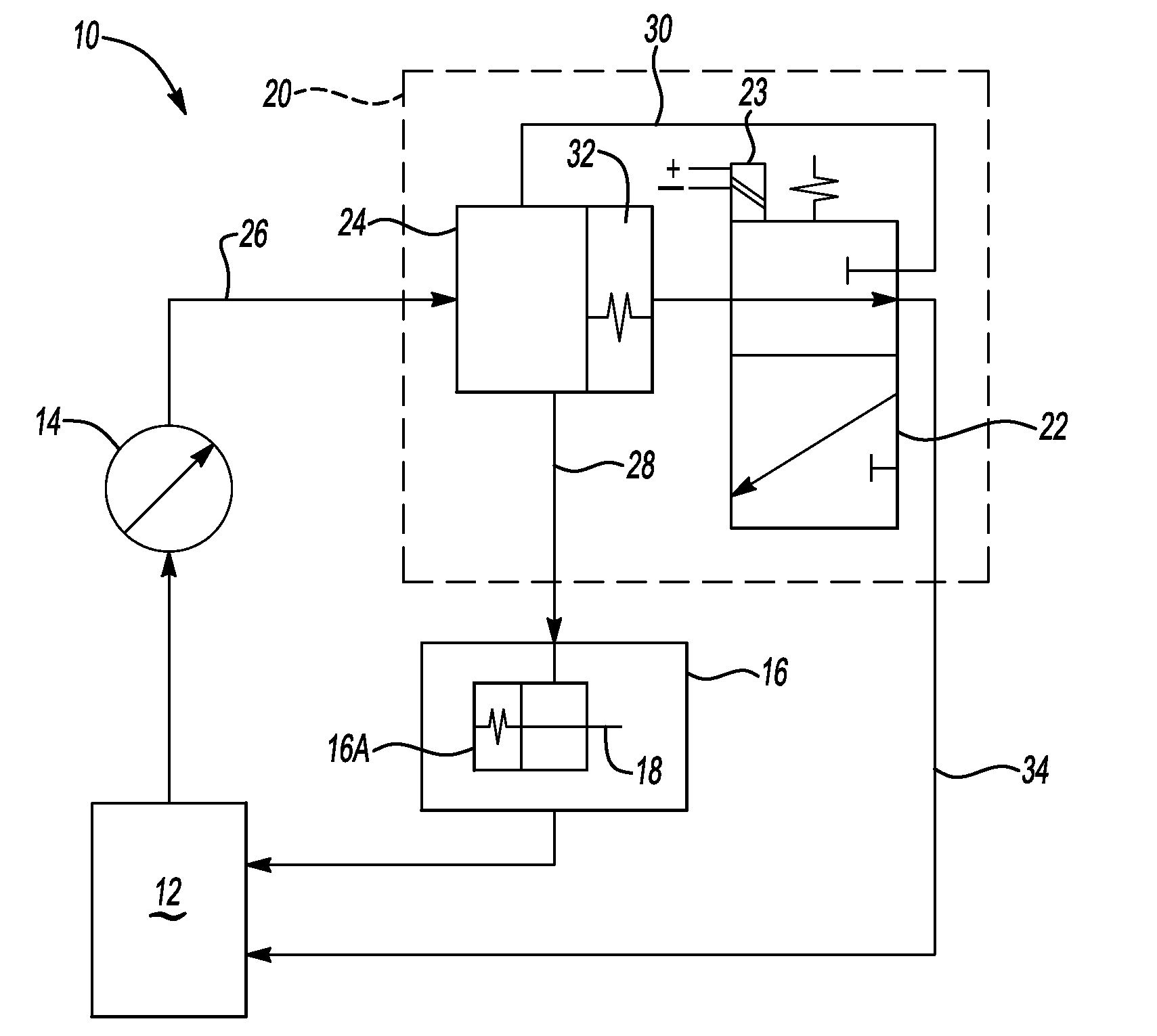
[0014]Referring to FIG. 1, wherein like reference numbers refer to the same or similar components throughout the several views, a hydraulic control system 10 is illustrated. The hydraulic control system 10 includes an oil reservoir 12 and an oil pump 14. The oil pump 14 pumps oil from the oil reservoir 12 to various engine components 16. The engine components 16 includes at least one engine component 16A which includes a latch pin 18 for actuation of the at least one engine component 16A between an engaged and disengaged position. The at least one engine component 16A could be a lash adjuster, a valve lifter, or a rocker arm. Although the embodiment described below is with reference to one latch pin 18, multiple latch pins 18 may be actuated at one time. The engine components 16 also include other valve-train components such as bearings.

[0015]Engagement and disengagement of the latch pin 18 within the at least one engine component 16A is actuated by the hydraulic control system 10 a...


PUM


Abstract

A hydraulic control system includes an oil control valve to control oil flow within a valvetrain. The control valve varies the flow rate to actuate an engine component from a first position to a second position based upon fluid pressure from the control valve. Varying the flow rate through the control valve includes increasing the flow rate through the control valve to increase the pressure to a first level to actuate the engine component to the first position. After the engine component is actuated, the flow rate through the control valve is maintained at a level sufficient to maintain the engine component in the first position. To actuate the engine component to the second position the flow rate through the control valve is then decreased. The fluid flow rate through the control valve is then maintained at a level sufficient to maintain the engine component in the second position.

Description

CROSS-REFERENCE TO RELATED APPLICATIONS[0001]This application claims the benefit of U.S. Provisional Application 61 / 082,575, filed Jul. 22, 2008, which is hereby incorporated by reference in its entirety.TECHNICAL FIELD[0002]The present invention relates to an oil control system for a valvetrain, and more specifically, to an arrangement and method for reducing oil consumption by the valve train.BACKGROUND OF THE INVENTION[0003]A hydraulic control system for an engine supplies oil to various engine components and may also include oil control valves to control oil under pressure that may be used to, for example, switch latch pins in switching lifters, switching rocker arms, and switching lash adjusters in engine valve train systems. Valve actuation systems include, but are not limited to, valve deactivation and variable valve lift systems.[0004]Valve lifters are engine components that transfer cam motion which controls the opening and closing of exhaust and intake valves in an engine....

Claims


Application Information

Patent Timeline
IPC IPC(8): F01L9/02E03B11/00F01L9/10
CPCF01L9/02F01L1/24G05D16/2093G05D16/2095Y10T137/7761Y10T137/776Y10T137/7768Y10T137/86196F01L9/10F01L13/00F01M1/16F16K31/40
Inventor KELLER, ROBERT D.BENEKER, GERRIT V.DAYTON, ROBERT A.
Owner EATON CORP
Why Eureka
Try Eureka