Power supply system and vehicle with the system

a technology of power supply system and power supply unit, which is applied in the direction of electric energy management, electric devices, and battery arrangement, etc., can solve the disadvantageous acceleration of power storage unit degradation, and achieve the effect of reducing the degradation of power storage uni

Active Publication Date: 2010-01-28
TOYOTA JIDOSHA KK
View PDF22 Cites 168 Cited by
  • Summary
  • Abstract
  • Description
  • Claims
  • Application Information

AI Technical Summary

Benefits of technology

[0012]An object of the present invention is to provide a power supply system capable

Problems solved by technology

Meanwhile, charging/discharging performance of the power storage unit much depends on the state of use, and over-charging or over-discharging leads to degradation.
Therefor

Method used


Image

  • Power supply system and vehicle with the system
  • Power supply system and vehicle with the system
  • Power supply system and vehicle with the system

Examples


embodiment 1

[0049](Schematic Configuration of Vehicle)

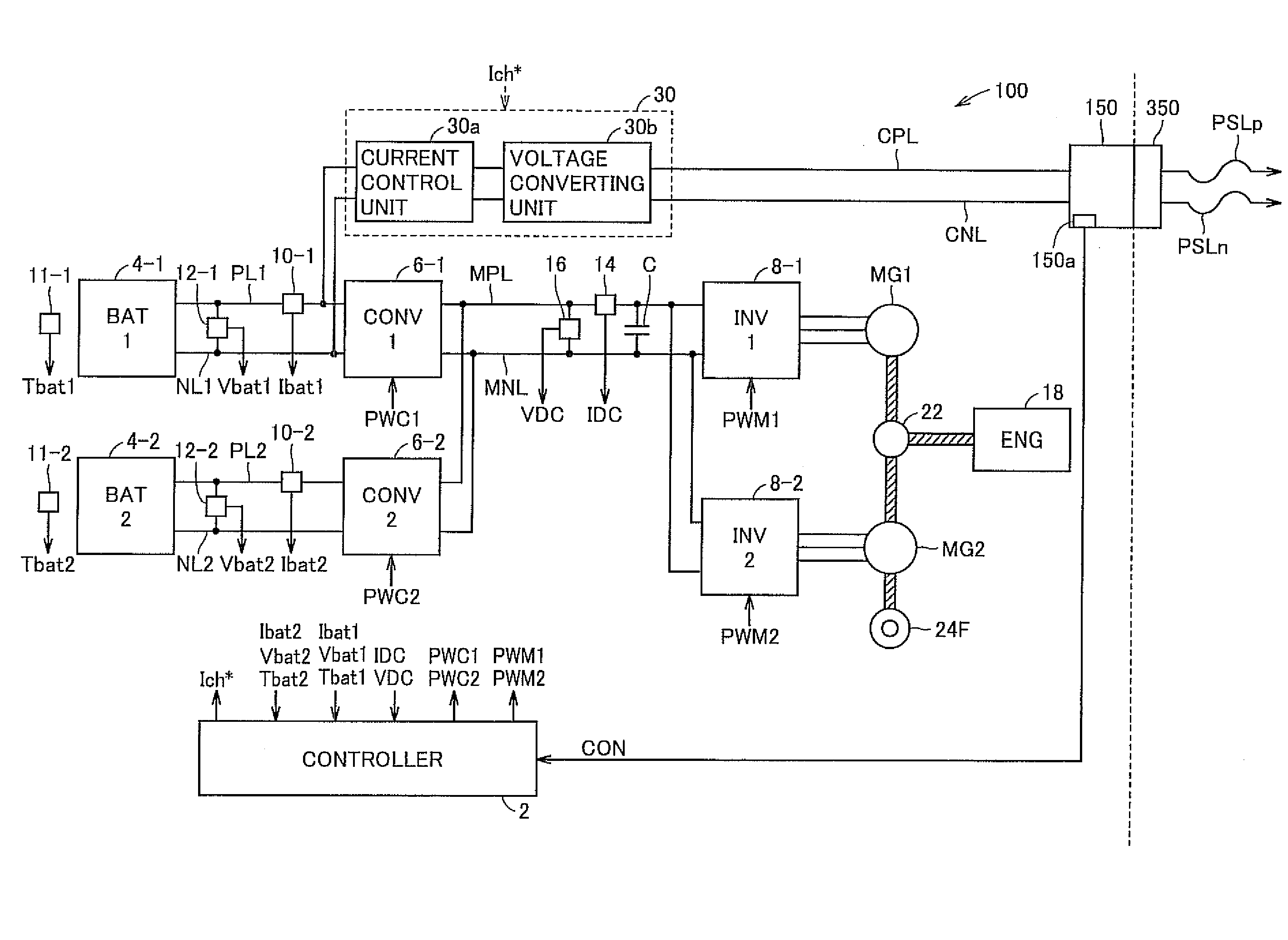
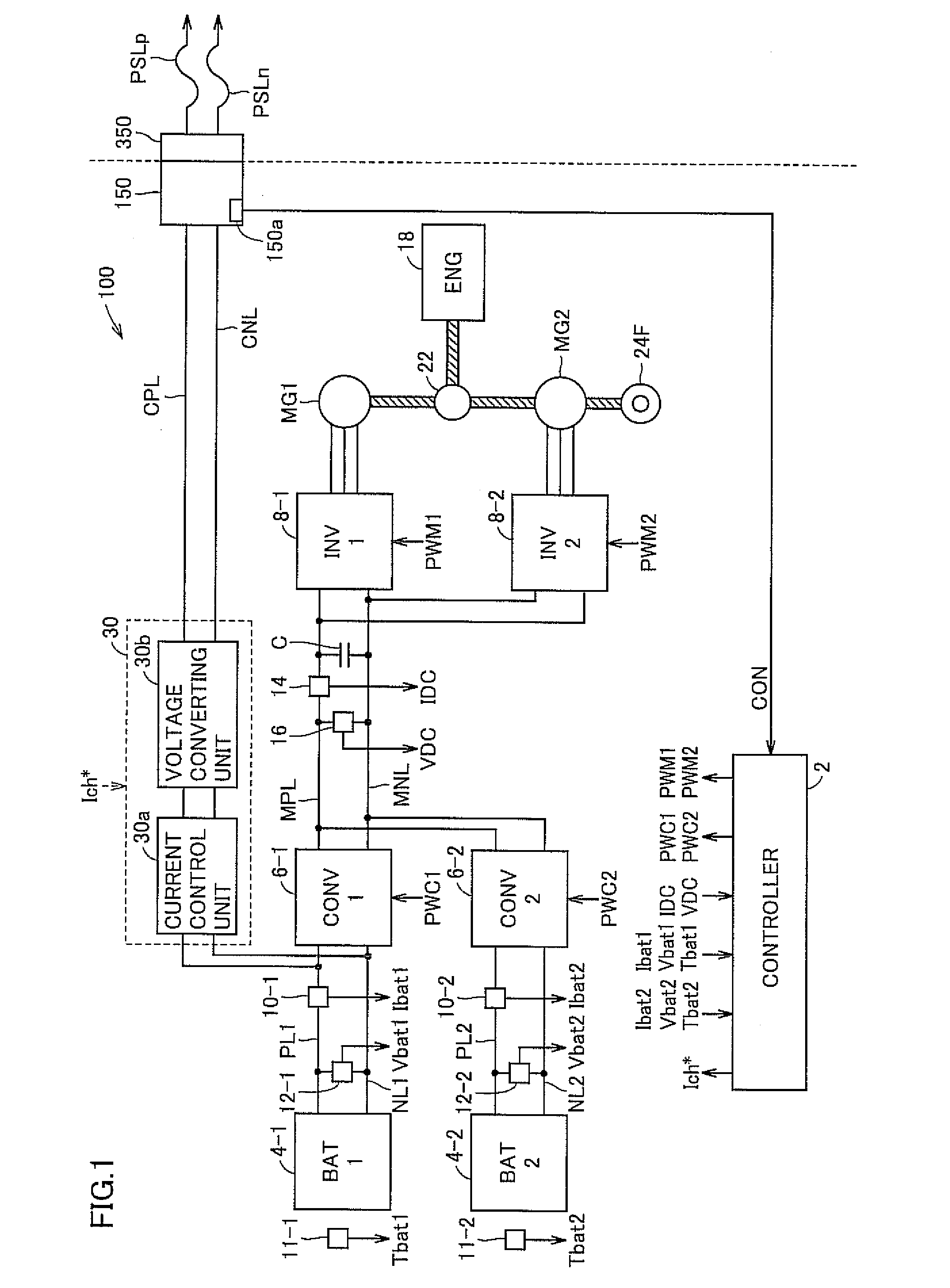
[0050]FIG. 1 is a schematic diagram showing a configuration related to charging by an external power source of a vehicle 100 mounting the power supply system in accordance with Embodiment 1 of the present invention.

[0051]Referring to FIG. 1, vehicle 100 in accordance with Embodiment 1 of the present invention is represented by a hybrid vehicle mounting an internal combustion engine (engine) and a motor generator (MG), which runs with driving powers from these adjusted to an optimal ratio. Further, vehicle 100 has a plurality of (for example, two) power storage units mounted thereon, for supplying electric power to the motor generator. In a system activated state (hereinafter also referred to as “IG on state”) of vehicle 100, these power storage units can be charged receiving power generated by an engine operation, and while the system of vehicle 100 is stopped (hereinafter also referred to as “IG off state”), the units can be electrically co...

embodiment 2

[0102]FIG. 5 is a block diagram showing a control structure of a controller 2A in accordance with Embodiment 2 of the present invention. Each of the functional blocks shown in FIG. 5 is typically realized by controller 2A executing a program stored in advance. It is noted, however, that part of or all of the functions may be implemented by dedicated hardware.

[0103]Referring to FIG. 5, controller 2A is equivalent to controller 2 in accordance with Embodiment 1 shown in FIG. 2 additionally including a target value correcting unit 220 and a battery temperature predicting unit 222 between target value setting unit 202 and converter control unit 210. Other portions of controller 2A have been described above and, therefore, detailed description will not be repeated.

[0104]Battery temperature predicting unit 222 estimates degree of increase of battery temperature during execution of external charging and thereby predicts battery temperatures Tbat1 and Tbat2 at the completion of external cha...

embodiment 3

[0128]In Embodiment 2 above, a configuration has been described in which the target state of charge is set in accordance with the expected battery temperature at the time of completion of external charging. By such a configuration, degradation of power storage unit can more effectively be reduced as compared with the configuration in which the power storage unit is uniformly charged to the fully charged state.

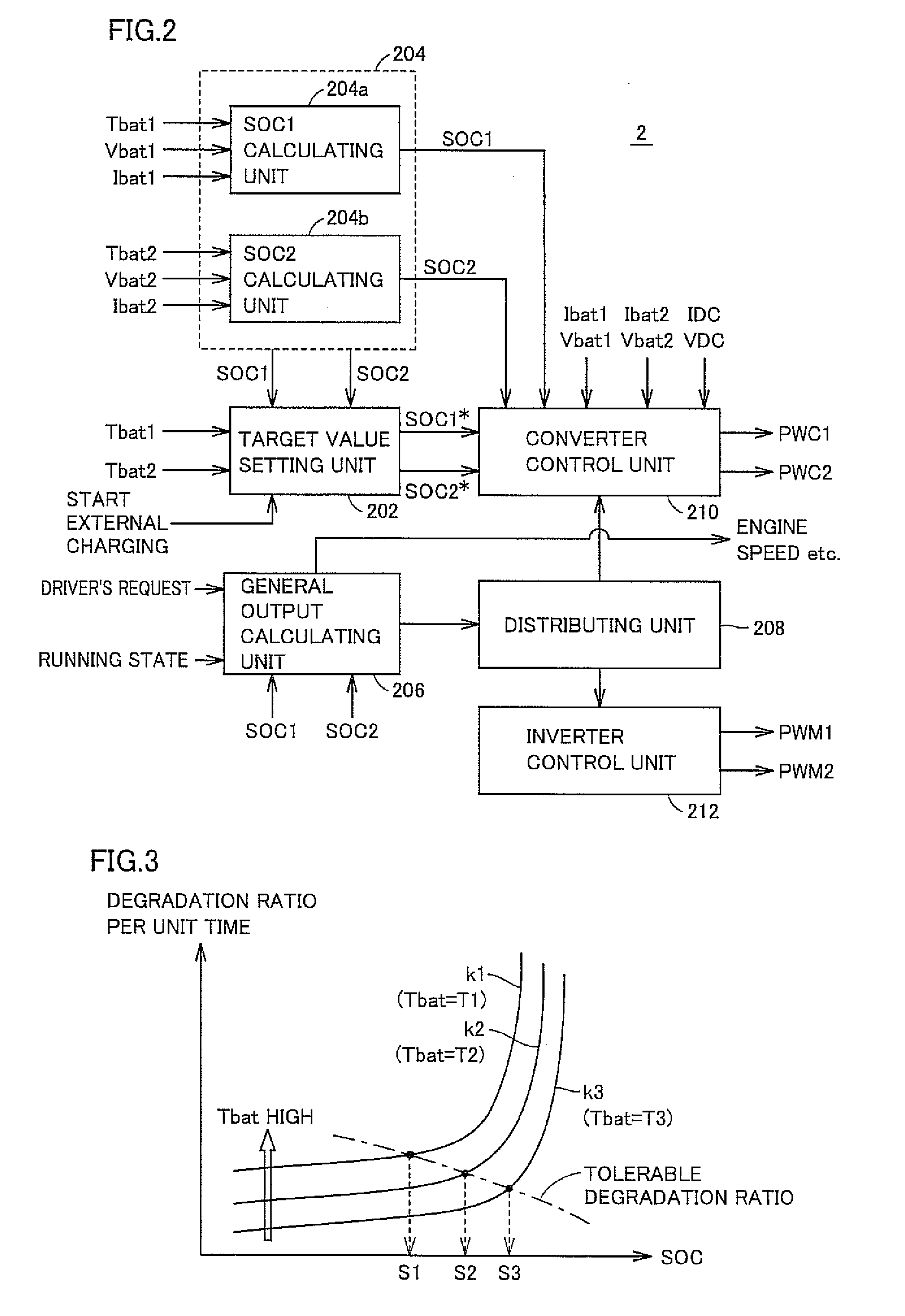
[0129]On the other hand, it follows that when the external charging is completed, the vehicle is left unused with the power storage unit having high SOC, until the vehicle next enters the IG on state. In this period, degradation proceeds. This is apparent from the degradation characteristic of power storage unit (FIG. 3) and, particularly when it is left unused with high battery temperature, accelerated degradation of power storage unit is expected.

[0130]Therefore, in Embodiment 3 below, a configuration will be described in which the target state of charge is set in considerati...


PUM


Abstract

A vehicle includes a charging unit receiving electric power from an external power source and externally charging a power storage unit. When a connector unit is coupled to the vehicle and a state ready for charging by the external power source is attained, a controller predicts degradation ratio of the power storage unit at the time point of completion of external charging based on degradation characteristic of the power storage unit in connection with SOC and battery temperature obtained in advance, and sets target state of charge of each power storage unit based on the battery temperatures so that the predicted degradation ratio does not exceed tolerable degradation ratio at the time point of completion of external charging. Then, the controller controls corresponding converters such that SOCs of power storage units attain the target states of charge.

Description

[0001]This nonprovisional application is based on Japanese Patent Application No. 2008-192405 filed on Jul. 25, 2008 with the Japan Patent Office, the entire contents of which are hereby incorporated by reference.BACKGROUND OF THE INVENTION[0002]1. Field of the Invention[0003]The present invention relates to a power supply system and a vehicle provided with the system and, more specifically, to a power supply system including a power storage unit and a vehicle provided with the same.[0004]2. Description of the Background Art[0005]Recently, considering environmental issues, vehicles using electric motors as driving power sources such as electric vehicles, hybrid vehicles and fuel cell vehicles have attracting attention. On such a vehicle, a power storage unit formed by a secondary battery or an electric double layer capacitor is mounted, for supplying electric power to the motor or for converting kinetic energy to electric energy for storage at the time of regenerative braking.[0006]...

Claims


Application Information

Patent Timeline
IPC IPC(8): H02J7/04B60L3/00B60L11/18H01M10/44H01M10/48H01M10/60H01M10/613H01M10/625H01M10/633H01M10/6563H01M10/663H02J7/00
CPCB60L11/123Y02T90/121B60L11/1824B60L11/1861B60L11/1872B60L2210/20B60L2260/56H02J7/0014H02J7/0054H02J7/02H02J7/1423H02J7/1461Y02T10/6217Y02T10/7005Y02T10/7044Y02T10/705Y02T10/7055Y02T10/7077Y02T10/725Y02T90/12Y02T90/127Y02T90/14Y02T10/84B60L11/14Y02T10/7072B60L50/61B60L50/16B60L53/30B60L58/25H02J7/342B60L58/15Y02T10/62Y02T10/70Y02T10/72H02J7/005H02J7/0049H02J5/00
Inventor KAITA, KEIJIIZUMI, JUNTA
Owner TOYOTA JIDOSHA KK
Why Eureka
Try Eureka