Three dimensional imaging method and apparatus

a three-dimensional imaging and three-dimensional imaging technology, applied in image analysis, instruments, maps/plans/charts, etc., can solve the problems of difficult identification and differentiation, low accuracy, and low accuracy of conventional devices, and achieve the effect of mapping huge areas cheaply and quickly

Inactive Publication Date: 2010-01-28
UNITED STATES OF AMERICA THE AS REPRESENTED BY THE SEC OF THE ARMY
View PDF4 Cites 36 Cited by
  • Summary
  • Abstract
  • Description
  • Claims
  • Application Information

AI Technical Summary

Benefits of technology

[0025]Although the technique is described with respect to vertical imaging from the air, the technique is just as applicable in the horizontal plane (for ground-based ladars, primarily). The key distinction is that the information to be visualized come from a sensor like a ladar that makes discrete measurements of the scene. Synthesizing or modeling has been the most common approach to creating 3-D scenes. However, ladars (both airborne and vehicle-carried) can map huge areas ...

Problems solved by technology

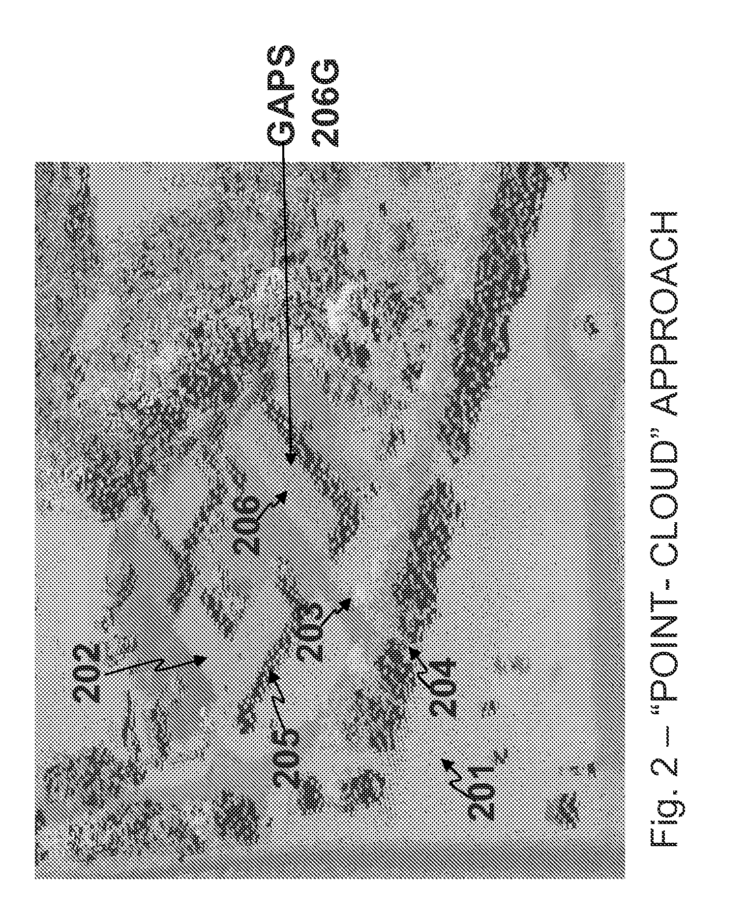
When imaging smaller-scale scenes, conventional devices tend to under-sample small-scale features, such as foliage, fences, railings, and light poles.
These features are difficult to identify and distinguish using the commonly employed terrain visualization techniques discussed above.
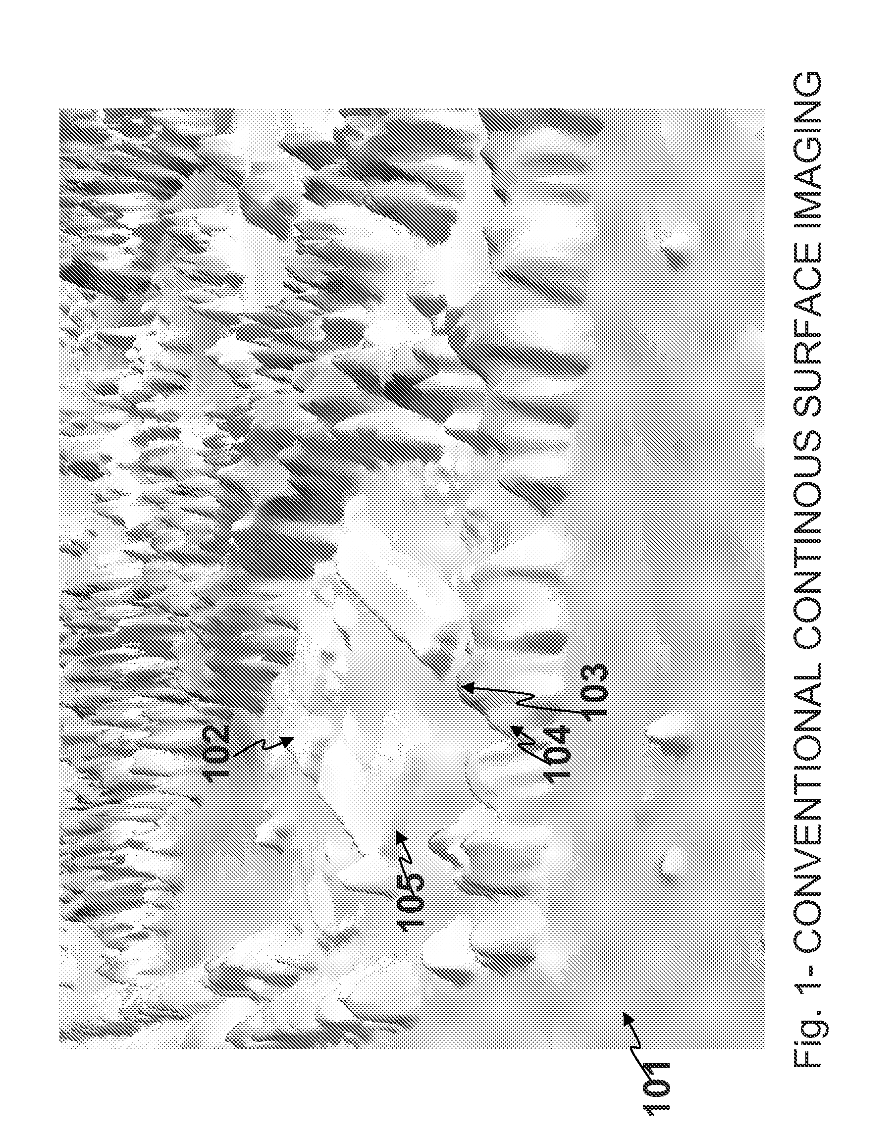
Unfortunately, this technique falls short when used to visualize terrain data at smaller scales; natural features such as bushes and trees can become indis...

Method used


Image

  • Three dimensional imaging method and apparatus
  • Three dimensional imaging method and apparatus
  • Three dimensional imaging method and apparatus

Examples


Embodiment Construction

[0051]The embodiments of the invention and the various features and advantageous details thereof are explained more fully with reference to the non-limiting embodiments that are illustrated in the accompanying drawings and detailed in the following description. It should be noted that the features illustrated in the drawings are not necessarily drawn to scale. Descriptions of well-known components and processing techniques are omitted so as to not unnecessarily obscure the embodiments of the invention. The examples used herein are intended merely to facilitate an understanding of ways in which the embodiments of the invention may be practiced and to further enable those of skilled in the art to practice the embodiments of the invention. Accordingly, the examples should not be construed as limiting the scope of the embodiments of the invention.

[0052]The terminology used herein is for the purpose of describing particular embodiments only and is not intended to limit the full scope of ...


PUM


Abstract

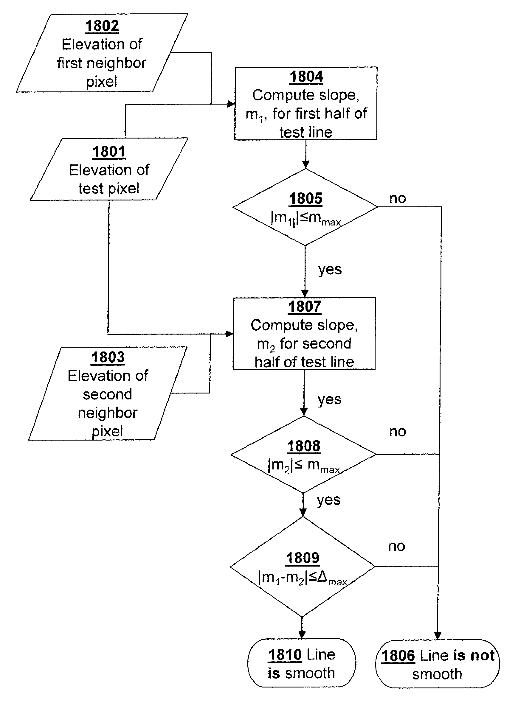
Three-dimensional imaging techniques are used for a visualization method and apparatus. In a preferred embodiment, terrain data is displayed as a series of pixels—areas of terrain elevation data. Individual pixels are analyzed to determine whether they are locally smooth or “warpable” relative to their surrounding neighbor pixels. Those pixels that are locally relatively “smooth,” i.e., those satisfying a given set of criteria, are joined with adjacent neighbor pixels by a process referred to herein as “warping” to create “smooth,” gap-free surfaces. A preferred embodiment includes drawing or generating lines between the centers of two pairs of adjacent pixels to determine a slopes m1 and m2 respectively. The slopes m1 and m2 are then analyzed using the following equations/determinations: |m1∥≦mmax; |m2∥≦mmax; and |m1−m2|≦Δmax; i.e., the slopes m1 and m2 must each be less than or equal to a predetermined threshold mmax and the difference between the slopes must be less than or equal to a predetermined difference Δmax.

Description

RELATED APPLICATIONS[0001]This application is a utility application claiming priority of U.S. Provisional Application Ser. No. 61 / 023,961 filed Jan. 28, 2008, entitled “A Novel Technique for Visualizing High-Resolution 3-D Terrain Maps,” which is incorporated herein by reference.GOVERNMENT INTEREST[0002]The invention described herein may be manufactured, used, and licensed by or for the United States Government.REFERENCE TO PARTIAL COMPUTER PROGRAM LISTING[0003]Appendix A contains a partial computer program listing adapted for a preferred embodiment of the present invention.REFERENCE TO COLOR DRAWINGS[0004]The patent or application file contains at least one drawing executed in color. Copies of this patent or patent application publication with color drawing(s) will be provided by the Office upon request and payment of the necessary fee.FIELD OF THE INVENTION[0005]This invention relates to digital terrain elevation techniques and / or three dimensional imaging techniques involving sce...

Claims


Application Information

Patent Timeline
IPC IPC(8): G06T15/00
CPCG06T19/00G01C11/02G06T7/0081G09B29/12G06T17/05G09B29/003G06T7/403G06T7/11G06T7/44
Inventor DAMMANN, JOHN F.
Owner UNITED STATES OF AMERICA THE AS REPRESENTED BY THE SEC OF THE ARMY
Why Eureka
Try Eureka