
Optical transmission system and optical transmission control method

Active Publication Date: 2010-01-28
NEC CORP
View PDF2 Cites 1 Cited by
  • Summary
  • Abstract
  • Description
  • Claims
  • Application Information

AI Technical Summary

Benefits of technology

[0012]The present invention has been made in view of the problems encountered by the conventional techniques as described above, and it is an object of the invention to provide an optical transmission system and an optical transmission control method which can be applied not only to a known signal but also to an unknown signal, and which are highly reliable and have a low cost.Means for Solving the Problem
[0021]A seventh effect provided by the present invention is the ability to sufficiently support not only a known signal but also an unknown signal. The reason for this is that a device for monitoring the degree of polarization is used in selecting a signal on a line which is less affected by polarization mode dispersion, without relying on a comparison with a reference signal.

Problems solved by technology

As the influence of polarization mode dispersion increases, signals cannot be normally transmitted / received in some cases.
However, in most cases, the realization of a multi-value optical modulation such as QPSK (Quadrature Phase Shift Keying) is accompanied by a high cost, an increase in the size of device, and technical difficulties.
Therefore, utilization of optical multi-value modulation gives rise to problems in terms of the cost, size, and the degree of technical difficulty.
While deterioration in the quality of transmission signals caused by the polarization mode dispersion is mitigated by utilizing a transmission channel which is less affected by polarization mode dispersion, replacement of a transmission channel involves a large scale construction work, and may lead to a situation where the provision of services can not but be interrupted in some cases.
Thus, problems arise in terms of cost and availability.
At present, no method is available for correctly monitoring the amount of polarization mode dispersion, including up to higher order components, in service, so that direct control cannot be conducted on the basis of the amount of polarization mode dispersion.
However, since factors causing a BER deterioration are not limited to polarization mode dispersion, it is necessary to extract the deterioration caused by the polarization mode dispersion from a BER deterioration amount, but such a method is not available at present.
In other words, correct polarization mode dispersion equalization control cannot be conducted with the use of BER information.
Accordingly, a waveform equalization scheme implies technical difficulties at present.
Also, any of the conventional techniques described above is limited in the amount of improvements in polarization mode dispersion immunity, and the amount of improvements is not often proportionate to the cost.

Method used


Image

  • Optical transmission system and optical transmission control method
  • Optical transmission system and optical transmission control method
  • Optical transmission system and optical transmission control method

Examples


Embodiment Construction

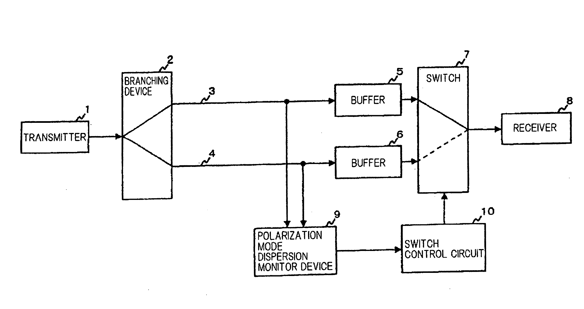
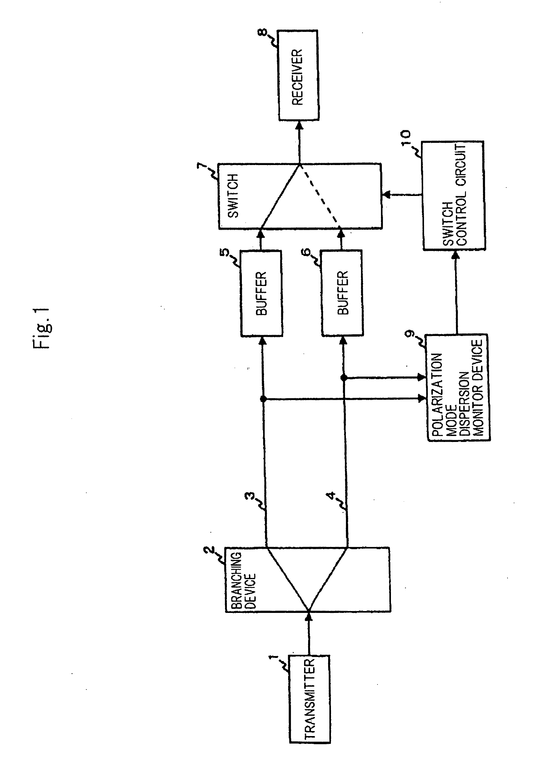
[0048]In the following, an embodiment of the present invention will be described with reference to the drawings. FIG. 1 is a general functional block diagram of an embodiment of the present invention.

[0049]In FIG. 1, an optical signal output from transmitter 1 is branched by branching device 2. The branched optical signals are led to optical transmission channels 3, 4, respectively. Then, each of these optical signals is input to switch 7 through reception buffer 5, 6, respectively.

[0050]Only one of the input optical signals is selected by switch 7, and is led to receiver 8. A switching control for switch 7 is implemented by switch control circuit 10. In this switch control circuit 10, the switching timing is determined from the result of monitoring polarization mode dispersion by polarization mode dispersion monitor device 9.

[0051]In the following, the operation of an optical signal quality monitoring device configured as described above will be described with reference to FIG. 1.

[...


PUM


Abstract

The present invention is intended to provide an optical transmission system which is applicable not only to a known signal but also to an unknown signal, and has a high reliability at a low cost. A branching device branches an optical transmission output of a transmitter, and transmits the branched signals through different optical transmission channels. A polarization mode dispersion monitor monitors the degree of polarization mode dispersion from the optical transmission channels at the receiving end. A switch control circuit and a switch select a signal which is less affected by a deterioration in quality due to polarization mode dispersion, and outputs the selected signal to receiver 8. In this way, the probability of a deterioration in the quality of a signal due to polarization mode dispersion can be reduced for a transmission signal.

Description

TECHNICAL FIELD[0001]The present invention relates to an optical transmission system and an optical transmission control method, and more particularly, to an optical transmission system which reduces the probability of failures caused by polarization mode dispersion.BACKGROUND ART[0002]In an optical transmission system, when signals are transmitted at higher rates on the order of several tens of Gbps, quality deterioration due to polarization mode dispersion becomes non-negligible. As the influence of polarization mode dispersion increases, signals cannot be normally transmitted / received in some cases. Approaches that are generally used to reduce the influence of polarization mode dispersion include devising a transmission signal modulation scheme, utilizing a transmission channel which is less affected by polarization mode dispersion, and compensating for waveform for distortion.[0003]One method of devising a transmission signal modulation scheme is to use multi-value modulation. A...

Claims


Application Information

Patent Timeline
IPC IPC(8): H04J14/02H04B10/2569
CPCH04B10/2569
Inventor TAKESHITA, HITOSHIITO, TOSHIHARU
Owner NEC CORP
Learn More