Mechanical process for creating particles in fluid

a technology of fluid and mechanical imprinting, which is applied in the field of mechanical imprinting and fluid field, can solve the problems of difficult to achieve good mechanical contact between the two plates over large surface areas, and the expensive lithography exposure system must be continuously used to optically

Inactive Publication Date: 2010-01-28
RGT UNIV OF CALIFORNIA
View PDF15 Cites 45 Cited by
  • Summary
  • Abstract
  • Description
  • Claims
  • Application Information

AI Technical Summary

Benefits of technology

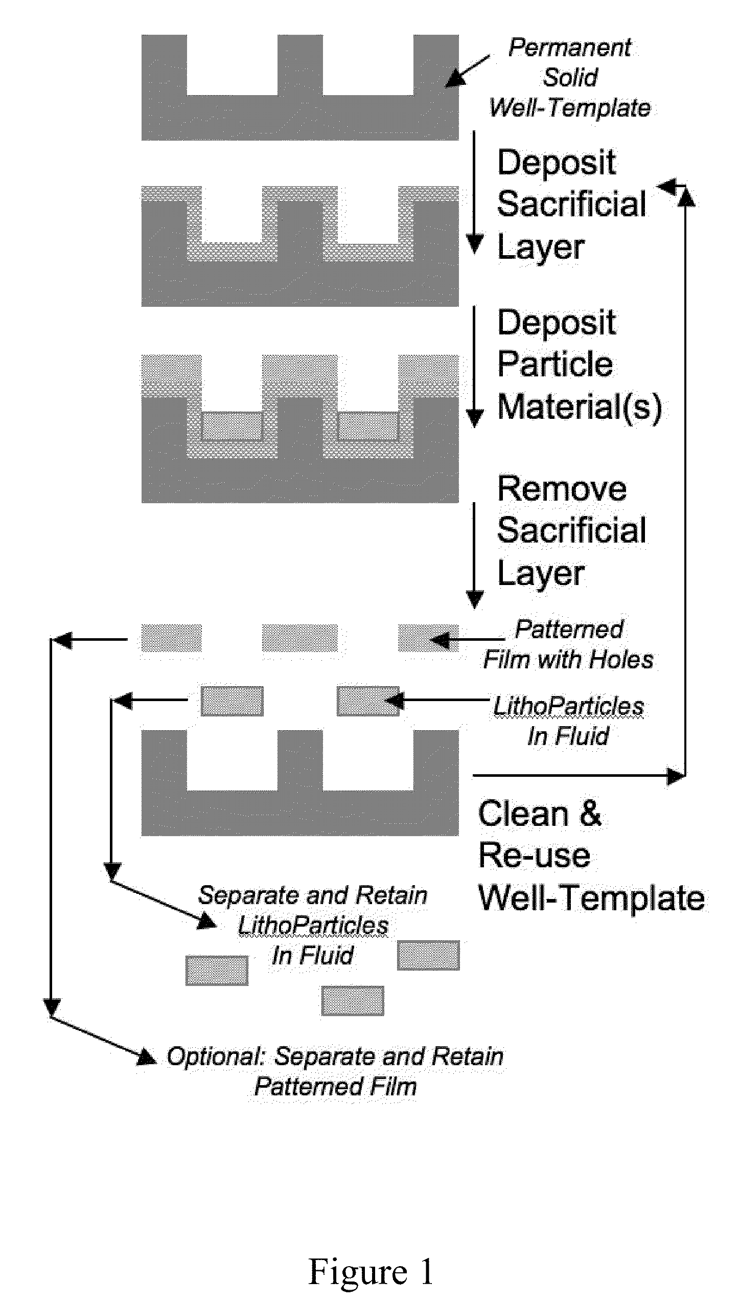
[0010]A method of producing at least one of microscopic and submicroscopic particles according to some embodiments of the current invention includes providing a template comprising a plurality of discrete surface portions, each discrete surface portion having a surface geometry selected to impart a desired geometrical property to a particle while being produced; depositing a constituent material of the at least one of microscopic and submicroscopic particles being produced onto the plurality of discrete surface portions of the template to form at least portions of the particles; separating the at least one of microscopic and submicroscopic particles comprising the constituent material

Problems solved by technology

Although robotically automated optical exposure can be used to create significant quantities of monodisperse LithoParticles, expensive lithography exposure systems must be continuously used to optically pattern films during the particle production process.
Performing mechanical imprinting reproducibly in a production setting can be problematic for many reasons.
It is often difficult to achieve good mechanical contact between the two plates over large surface areas.
Using pedestals decreases t

Method used


Image

  • Mechanical process for creating particles in fluid
  • Mechanical process for creating particles in fluid
  • Mechanical process for creating particles in fluid

Examples


Embodiment Construction

[0065]In describing embodiments of the present invention illustrated in the drawings, specific terminology is employed for the sake of clarity. However, the invention is not intended to be limited to the specific terminology so selected. It is to be understood that each specific element includes all technical equivalents which operate in a similar manner to accomplish a similar purpose.

[0066]Some embodiments of the current invention provide methods for producing microscopic and / or submicroscopic particles. The methods according to some embodiments of the current invention include providing a template that has a plurality of discrete surface portions, each discrete surface portion having a surface geometry selected to impart a desired geometrical property to a particle while being produced. Each of the discrete surface portions can be, but are not limited to, a flat surface, a curved surface, a complex contoured surface, a surface with a plurality of subsurface regions, or any combin...


PUM

PropertyMeasurementUnit
Lengthaaaaaaaaaa
Lengthaaaaaaaaaa
Thicknessaaaaaaaaaa

Abstract

A method of producing at least one of microscopic and submicroscopic particles includes providing a template that has a plurality of discrete surface portions, each discrete surface portion having a surface geometry selected to impart a desired geometrical property to a particle while being produced; depositing a constituent material of the at least one of microscopic and submicroscopic particles being produced onto the plurality of discrete surface portions of the template to form at least portions of the particles; separating the at least one of microscopic and submicroscopic particles comprising the constituent material from the template into a fluid material, the particles being separate from each other at respective discrete surface portions of the template; and processing the template for subsequent use in producing additional at least one of microscopic and submicroscopic particles. A multi-component composition includes a first material component in which particles can be dispersed, and a plurality of particles dispersed in the first material component. The plurality of particles is produced by methods according to embodiments of the current invention.

Description

CROSS-REFERENCE TO RELATED APPLICATION[0001]This application claims priority to U.S. Provisional Application No. 61 / 100,471 filed Sep. 26, 2008. This application is a Continuation-in-Part of PCT / US2008 / 003679, filed Mar. 20, 2008, which claims priority to U.S. Provisional Application No. 60 / 918,896, filed Mar. 20, 2007. The entire contents of all the above documents are hereby incorporated by reference.[0002]This invention was made with Government support under Grant No. CHE-0450022 awarded by the National Science Foundation. The Government has certain rights in this inventionBACKGROUND[0003]1. Field of Invention[0004]This application relates to processes and systems for making particles, and more particularly processes and systems for making particles having a dimension less than about 1 mm.[0005]2. Discussion of Related Art[0006]The contents of all references, including articles, published patent applications and patents referred to anywhere in this specification are hereby incorp...

Claims


Application Information

Patent Timeline
IPC IPC(8): B05D7/00B05C11/00C23C14/34C09D11/00H01F1/00C09K3/00C08K9/00C09D189/00C09D103/00C12N11/00C12N7/00
CPCB82Y25/00H01F1/009H01F1/0054B22F9/12B29B9/10H01F1/44
Inventor MASON, THOMAS G.
Owner RGT UNIV OF CALIFORNIA
Why Eureka
Try Eureka