
Use Of Graphs To Decompose Layout Design Data

a layout design and data technology, applied in the field of layout design data decomposition, can solve the problems of difficult to determine the shape of the polygon in the target, physical size of the polygon, and difficulty in properly manufacturing adjacent device components in a single lithographic process

Inactive Publication Date: 2010-01-28
SAHOURIA EMILE Y +1
View PDF8 Cites 35 Cited by
  • Summary
  • Abstract
  • Description
  • Claims
  • Application Information

AI Technical Summary

Benefits of technology

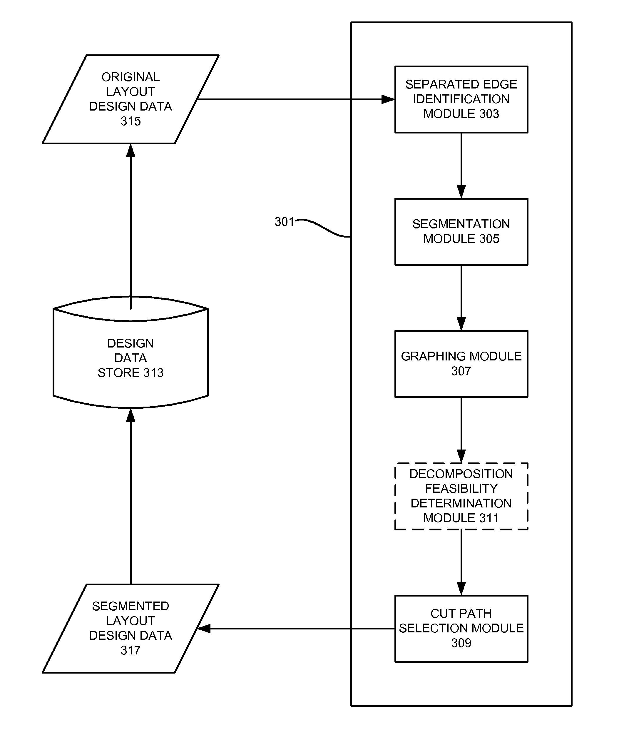
[0014]Aspects of the invention relate to techniques for determining if the decomposition of layout design data is feasible. Other aspects of the invention relate to techniques for optimizing the segmentation of polygons in decomposable layout design data. According to various implementations of the invention, layout design data is analyzed to identify the edges of polygons that should be imaged by separate lithographic masks. These “separated” edges may be automatically or manually specified using, for example, a separation directive. In addition, proposed cut paths are generated to cut the polygons in the layout design data into a plurality of polygon segments.
[0015]Once the separated edges and cut paths have been selected, a conflict graph is constructed that reflects these relationships. More particularly, each polygon segment is represented by a node in the conflict graph. Nodes representing polygon segments that have separated polygon edges are connected by a first type of graph edge, referred to hereafter as a separation graph edge. That is, if a polygon segment has an edge that should be formed with a different mask than the edge of an adjacent polygon segment, the nodes representing those polygon segments will be linked in the conflict graph by a separation graph edge. Nodes representing abutting polygon segments similarly are connected by a second type of edge, referred to hereafter as a cut path graph edge. Thus, each pair of separated polygon edges will have a corresponding separation graph edge in the conflict graph, and each cut path will have a corresponding cut path graph edge in the conflict graph.
[0016]Next, a dual of the conflict graph is constructed. This dual graph will have separation dual graph edges corresponding to the separation graph edges of the conflict graph. It also will have cut path dual graph edges corresponding to the cut path graph edges of the conflict graph. Thus, the dual graph will have a corresponding separation dual graph edge for each separated polygon edge pair in the layout design data. The dual graph also will have a corresponding cut path dual graph edge for each proposed cut path generated for the layout design data.
[0017]After the dual graph has been constructed, it is analyzed to determine which of the proposed cut paths should be kept and which should be discarded. First, those nodes in the dual graph that have an odd number of incident separation dual graph edges (referred to herein as “odd” nodes) are identified, as are the nodes that have an even number of incident separation dual graph edges (referred to herein as “even” nodes). After these nodes have been identified, then the cut path dual graph edges that pass through even numbers of even nodes to join pairs of odd nodes are selected. According to various implementations of the invention, for example, this is accomplished by assigning weights to the cut path dual graph edges and selecting the cut path dual graph edges that make up the cut path dual graph edge minimum-weight T-join of the odd nodes.
[0018]The selected cut path dual graph edges correspond to the cut paths that should be used to decompose the layout design data. With some implementations of the invention, the layout design data is modified to include the cut paths corresponding to the selected cut path dual graph edges. Still other implementations of the invention may alternately or additionally create separate sets of layout design data decomposed from original layout design data using the selected cut paths. For example, some implementations of the invention may output a first set of layout design data to form a first mask, and a second set of layout design data used to form a second mask complementary to the first mask. Both masks can then be used to form all of the structures described in the original layout design data.

Problems solved by technology

Moreover, the sizes of the polygons are limited physically by the maximum beam (or beam array) size available to the tool.
Some current microcircuit designs call for microcircuit devices to be packed so closely that it may be difficult to properly manufacture adjacent device components in a single lithographic process.
For example, a current microcircuit design may specify a series of parallel conductive lines positioned so closely that a conventional mask writer cannot resolve the pitch between the lines.
It is often difficult, however, to determine how the polygons in the target pattern should be segmented, i.e., where to cut the polygons.

Method used


Image

  • Use Of Graphs To Decompose Layout Design Data
  • Use Of Graphs To Decompose Layout Design Data
  • Use Of Graphs To Decompose Layout Design Data

Examples


Embodiment Construction

Operating Environment

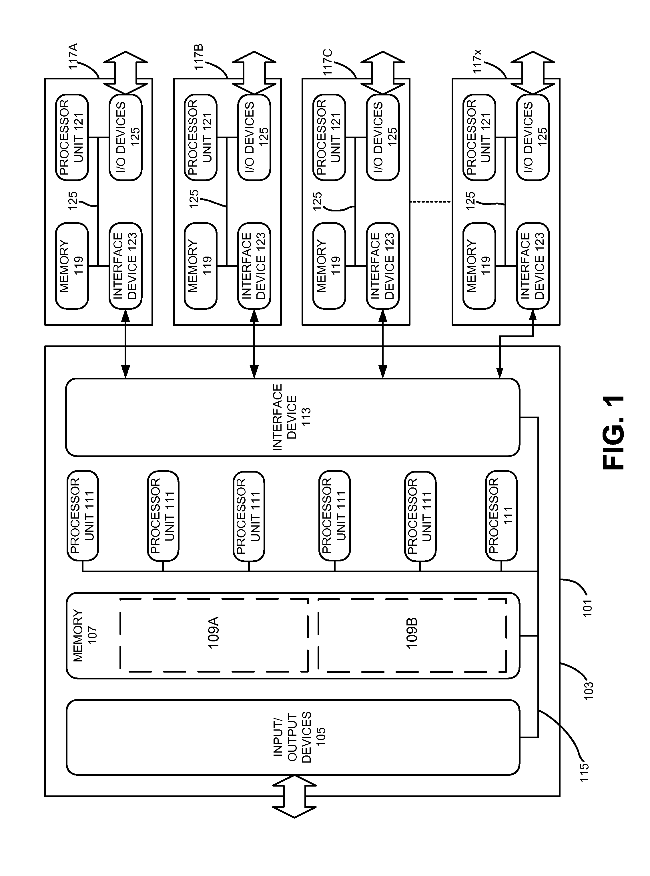
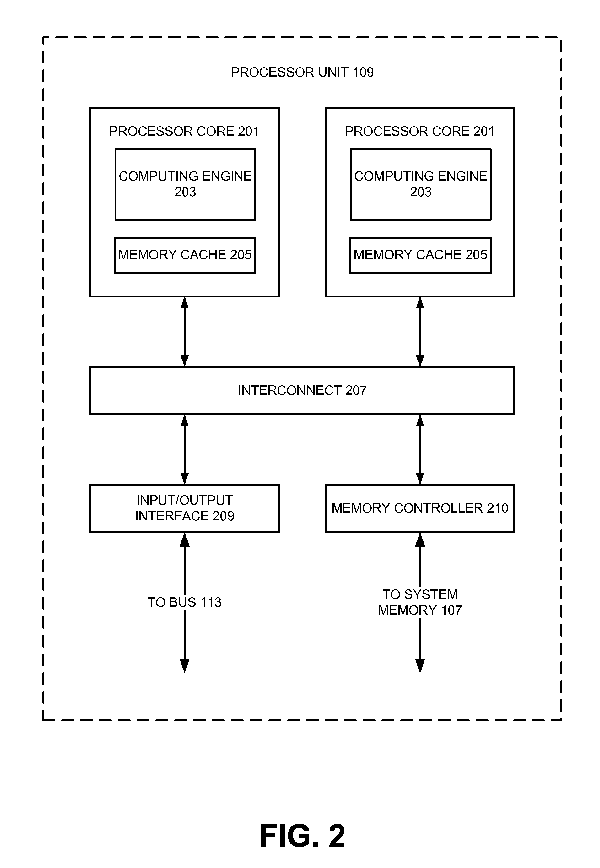
[0031]The execution of various electronic design automation processes according to embodiments of the invention may be implemented using computer-executable software instructions executed by one or more programmable computing devices. Because these embodiments of the invention may be implemented using software instructions, the components and operation of a generic programmable computer system on which various embodiments of the invention may be employed will first be described. Further, because of the complexity of some electronic design automation processes and the large size of many circuit designs, various electronic design automation tools are configured to operate on a computing system capable of simultaneously running multiple processing threads. The components and operation of a computer network having a host or master computer and one or more remote or servant computers therefore will be described with reference to FIG. 4. This operating environment is ...


PUM


Abstract

Techniques are disclosed for determining if the decomposition of layout design data is feasible, and for optimizing the segmentation of polygons in decomposable layout design data. Layout design data is analyzed to identify the edges of polygons that should be imaged by separate lithographic masks. In addition, proposed cut paths are generated to cut the polygons in the layout design data into a plurality of polygon segments. Once the separated edges and cut paths have been selected, a conflict graph is constructed that reflects these relationships. Next, a dual of the conflict graph is constructed. This dual graph will have a corresponding separation dual graph edge for each separated polygon edge pair in the layout design data. The dual graph also will have a corresponding cut path dual graph edge for each proposed cut path generated for the layout design data. After the dual graph has been constructed, it is analyzed to determine which of the proposed cut paths should be kept and which should be discarded. The layout design data is then modified to include the cut paths corresponding to the selected cut path dual graph edges. Alternately or additionally, separate sets of layout design data may be decomposed from original layout design data using the selected cut paths.

Description

RELATED APPLICATIONS[0001]This application claims priority under 35 U.S.C. §119 to U.S. Provisional Patent Application No. 61 / 030,100, filed on Feb. 20, 2008, entitled “Use Of Graphs To Decompose Layout Design Data” and naming Emile Y. Sahouria and Petr Glotov as inventors, which application is incorporated entirely herein by reference.FIELD OF THE INVENTION[0002]The present invention is directed to the use of graphs to decompose the geometric elements in a layout design. Various aspects of the invention may be particularly beneficial for partitioning geometric elements in a layer of a layout design data into separate groups. The groups can then be used to create complementary masks for use in a double-patterning manufacturing process.BACKGROUND OF THE INVENTION[0003]Electronic circuits, such as integrated microcircuits, are used in a variety of products, from automobiles to microwaves to personal computers. Designing and fabricating microcircuit devices typically involves many step...

Claims


Application Information

Patent Timeline
Patent Type & Authority Applications(United States)
IPC IPC(8): G06F17/50
CPCG03F1/144G03F1/70
Inventor SAHOURIA, EMILE Y.GLOTOV, PETR E.
Owner SAHOURIA EMILE Y
Learn More