Method of considering the dynamic behavior of a movable member of a machine for performing a wheel fatigue test

Inactive Publication Date: 2010-02-04
GKN LAND SYST
View PDF6 Cites 8 Cited by
  • Summary
  • Abstract
  • Description
  • Claims
  • Application Information

AI Technical Summary

Benefits of technology

[0014]In particular it has been found that under dynamic conditions, a displacement of a centre of gravity of the hub-carrying shaft may occur due to the flexibility of components of the machine, and which displacement is greatly influenced by the weight of the eccentrically mounted mass and the speed of rotation of the drive shaft. This can cause a s

Problems solved by technology

It has been found that the prior art methodology and machine used in wheel fatigue testing did not take into account that based on calibration under static conditions, there relationship between actual moments and sensor, e.g. strain gauge readings, is not linear.

Method used


Image

  • Method of considering the dynamic behavior of a movable member of a machine for performing a wheel fatigue test
  • Method of considering the dynamic behavior of a movable member of a machine for performing a wheel fatigue test
  • Method of considering the dynamic behavior of a movable member of a machine for performing a wheel fatigue test

Examples


Embodiment Construction

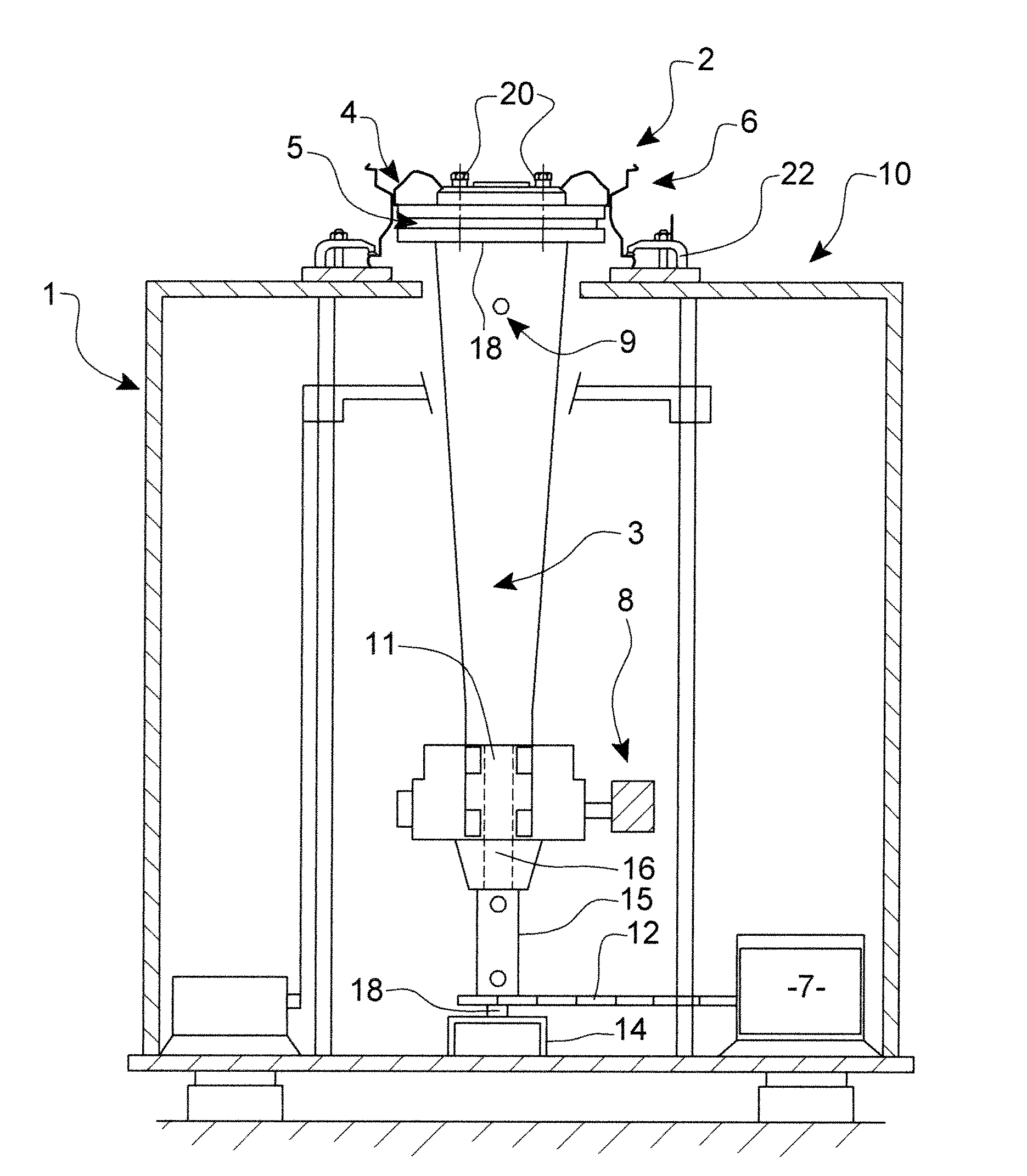
[0040]The machine 10 shown in FIG. 1 has been described above.

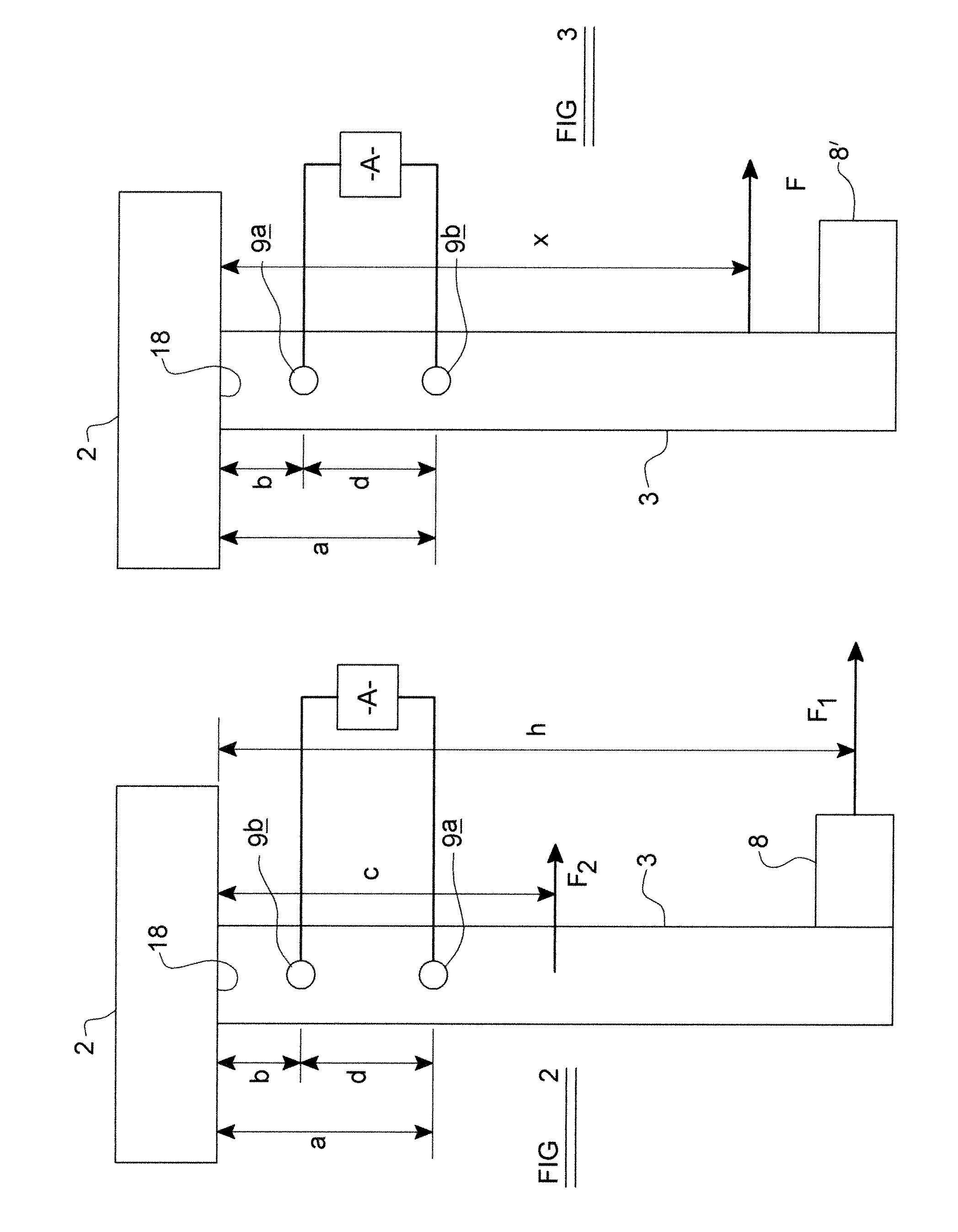
[0041]In FIG. 2 the machine 10, is shown more diagrammatically, and has been modified in accordance with the invention.

[0042]The testing machine 10 of FIG. 2, is substantially similar to that of FIG. 1, even though the configuration of the various machine 10 parts, and the wheel 2 under test are shown with less detail.

[0043]The modification to the FIG. 1 testing machine 10 which is made in FIG. 2, is the provision of first and second strain gauges 9a and 9b rather than the single strain gauge 9, with each of the two strain gauges 9a and 9b being connected operatively, to an analysing apparatus A which includes a processor, which from both of the signals from the strain gauges 9a, 9b determines more accurately the bending moment applied to the wheel 2 during testing, than is achievable with the FIG. 1 machine 10.

[0044]The first and second strain gauges 9a, 9b are substantially aligned. In the example in which the movable m...


PUM


Abstract

A method of considering the dynamic behaviour of a movable member of a machine for performing a wheel fatigue test, the wheel including a disc and a rim, the method including mounting the wheel by fixing the wheel rim relative to a fixed structure of the machine, and securing the disc relative to the movable member which is movable to transmit a cyclical bending moment to the wheel, exerting a cyclical force on the movable member to generate the bending moment, at a distant position from the wheel, and while exerting the cyclical force, determining an indication of bending moment in the movable member at a first position between the wheel and the distant position, determining an indication of bending moment in the movable member at a second position between the first position and the distant position, and using the indications of bending moment at both of the first and second positions to determine an actual bending moment applied to the wheel.

Description

BACKGROUND OF THE INVENTION [0001]This invention relates to a method of considering the dynamic behaviour of a movable member of a machine for performing a wheel fatigue test, and more particularly to a method of determining a bending moment applied to the wheel as the member moves.[0002]Wheels typically are constituted by two main parts namely a circular rim to which in use, a tyre is mounted, and a disc by means of which the wheel is securable to a hub of a vehicle. In order to predict the service life of a wheel of a particular design, it is known to conduct a fatigue test which involves clamping the rim to a fixed structure and attaching the disc to a member which moves to apply a bending moment to the wheel. Accurate determination of the bending moment applied is required for the testing method.DESCRIPTION OF THE PRIOR ART[0003]Referring to FIG. 1 a typical existing machine for performing a wheel fatigue test is shown at 10. The machine 10 includes a member which in this exampl...

Claims


Application Information

Patent Timeline
IPC IPC(8): G01N3/32
CPCG01M17/013G01N2203/0023G01N3/32G01N33/0085
Inventor CRAGG, STEPHEN R.
Owner GKN LAND SYST
Why Eureka
Try Eureka