Methods and systems for detecting sensor fault modes

a technology of fault mode and sensor, applied in the direction of motors, wind energy generation, instruments, etc., can solve the problems of reducing the risk of sensor entering a fault mode, affecting the operation of the motor, so as to reduce the risk of undue reliance on the sensor

Active Publication Date: 2013-05-02
VESTAS WIND SYST AS
View PDF9 Cites 58 Cited by
  • Summary
  • Abstract
  • Description
  • Claims
  • Application Information

AI Technical Summary

Benefits of technology

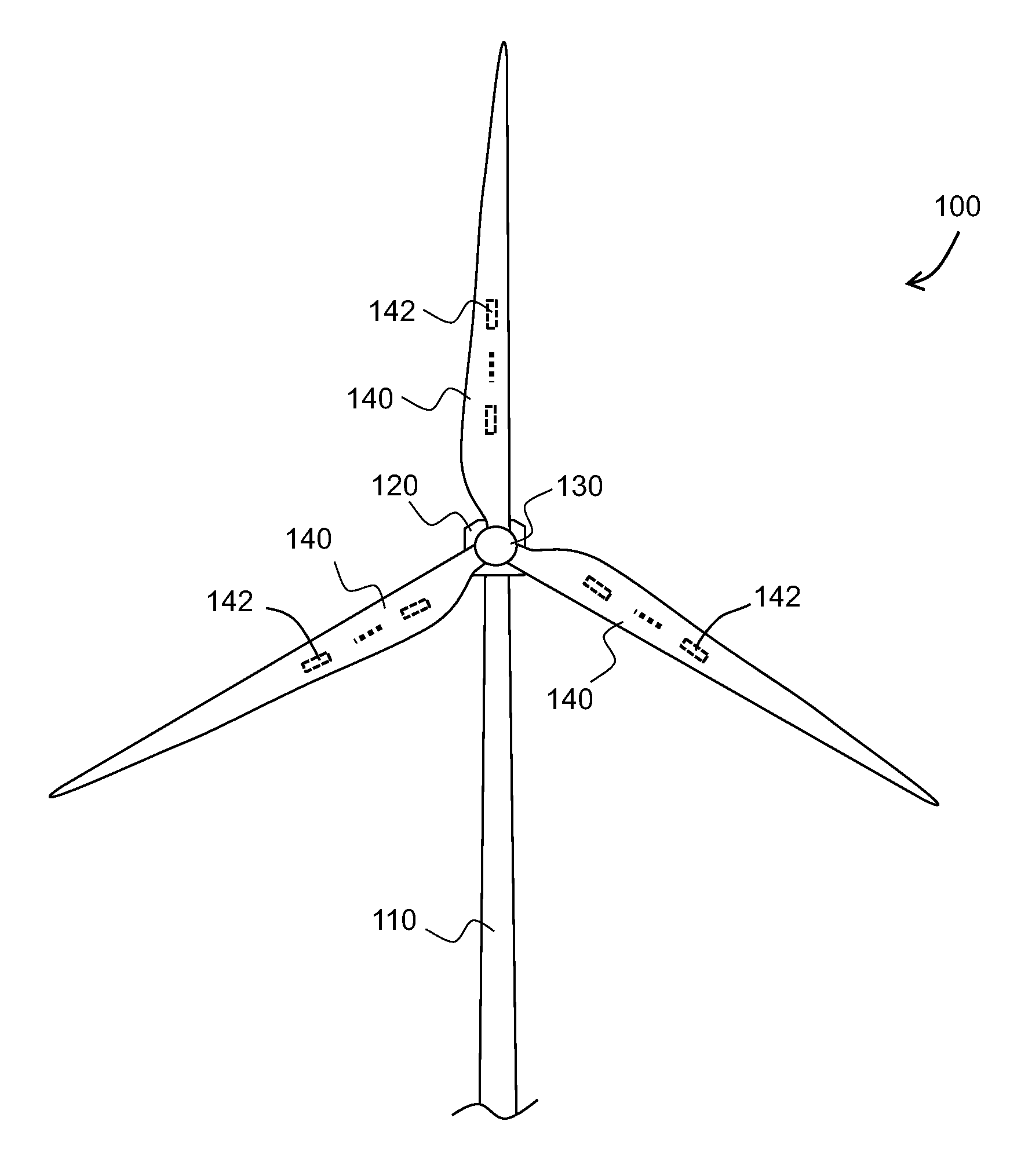
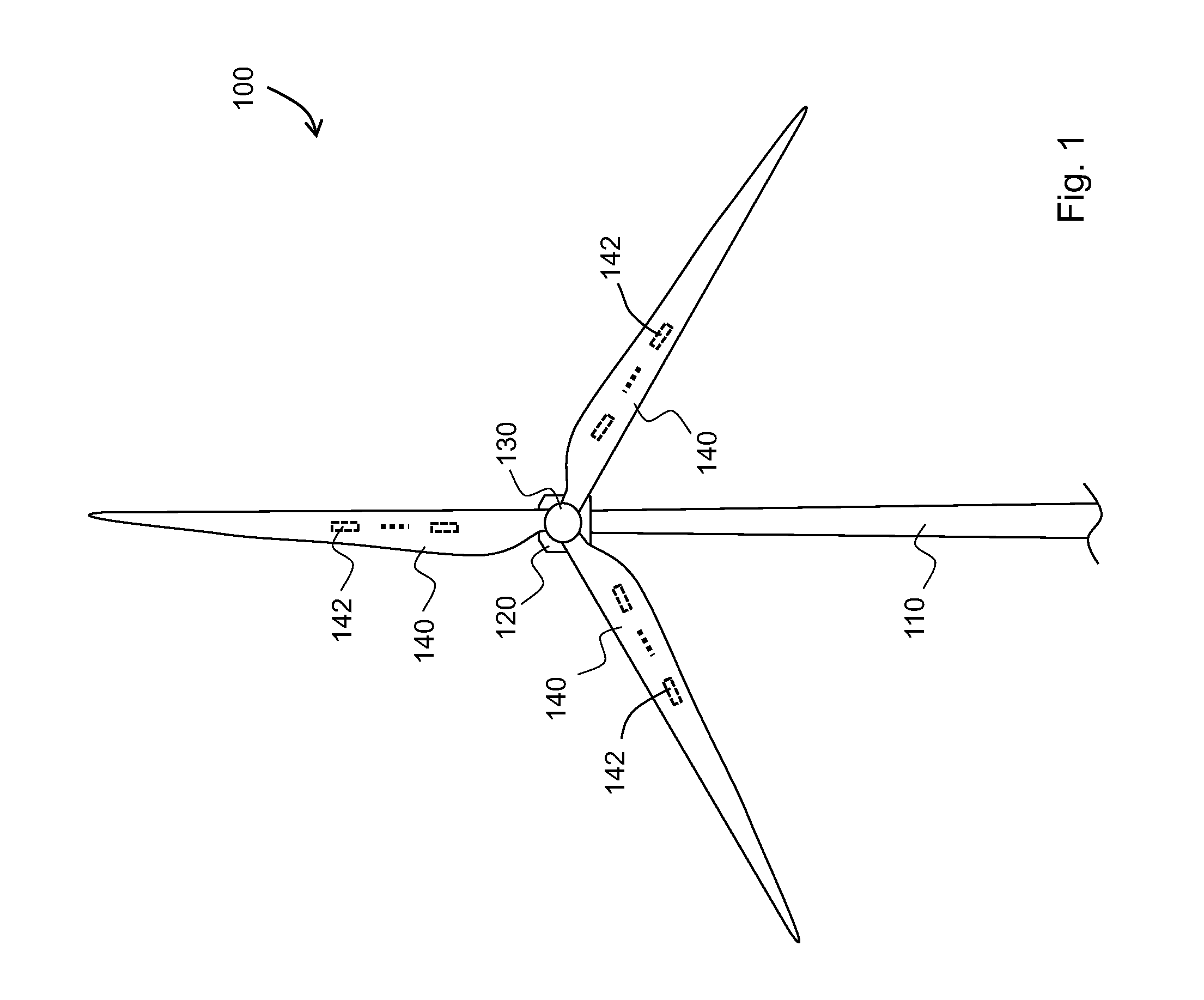
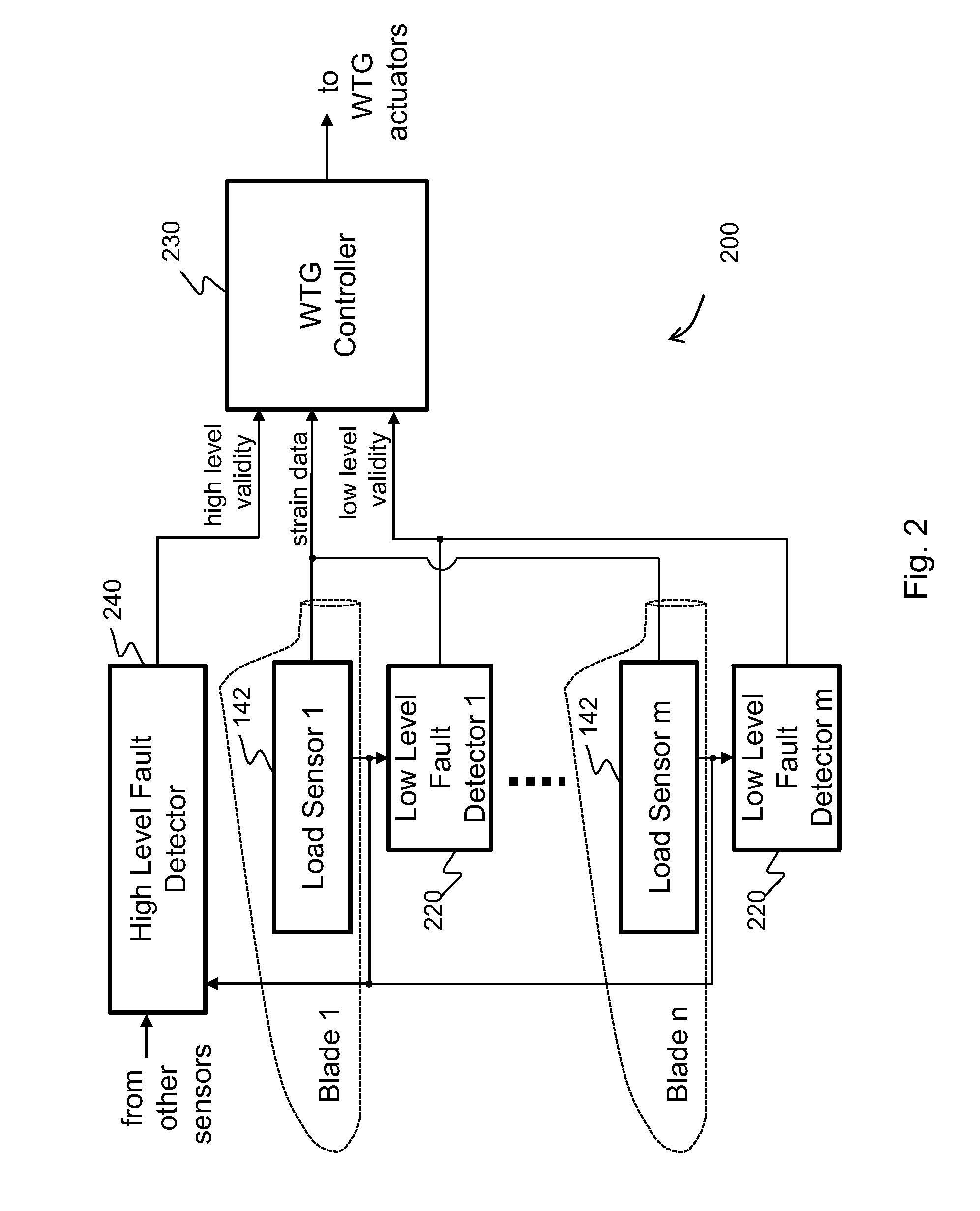
[0006]According to a first aspect the invention provides a method of detecting a fault mode of a sensor. The sensor may be, for example, a bending moment sensor and may sense a bending moment of a blade on a wind turbine generator (WTG). The method includes comparing data output by a first sensor with reference data indicating what is expected to be output by the first sensor to produce a first comparison result and comparing data output by the first sensor with data output by a second sensor to produce a second comparison result. A determination of whether the first sensor has entered a fault mode is made based at least in part on the first and second comparison results. By detecting a fault mode of the sensor the risk of undue reliance on the sensor may be reduced in a timely manner without the need for technician servicing.

Problems solved by technology

While some bending is expected, the blade can suffer damage if it bends beyond an extreme limit or too frequently.
The risk of such damage is greater in proportion to the ever increasing size of blades used in modern WTGs.
One problem associated with the use of any sensor is the risk of the sensor entering a fault mode.
Thus, risk of failure or poor performance for any such systems will increase if the sensor enters a fault mode.
Moreover, reducing risk of failure and poor performance is useful for modern WTGs because they operate in remote locations, making technician servicing difficult and costly, and are often required to have long operational lifetimes, e.g., twenty years.
Other sensor fault modes may occur, however, such as partial or complete loss of power in the sensor output, loss of sensor calibration, and / or signal processing errors.
Moreover, fault modes of a sensor may manifest at a high level (i.e., at a level that takes into account external data or data other than that available from the sensor) or at a low level (i.e., at a level that takes into account internal data or data available from or pertaining to only the sensor).

Method used


Image

  • Methods and systems for detecting sensor fault modes
  • Methods and systems for detecting sensor fault modes
  • Methods and systems for detecting sensor fault modes

Examples


Embodiment Construction

[0028]The following is a detailed description of embodiments of the invention depicted in the accompanying drawings. The embodiments are examples and are in such detail as to clearly communicate the invention. However, the amount of detail offered is not intended to limit the anticipated variations of embodiments; but on the contrary, the intention is to cover all modifications, equivalents, and alternatives falling within the spirit and scope of the present invention as defined by the appended claims.

[0029]Furthermore, in various embodiments the invention provides numerous advantages over the prior art. However, although embodiments of the invention may achieve advantages over other possible solutions and / or over the prior art, whether or not a particular advantage is achieved by a given embodiment is not limiting of the invention. Thus, the following aspects, features, embodiments and advantages are merely illustrative and are not considered elements or limitations of the appended...


PUM


Abstract

A method of detecting a fault mode of a sensor is provided. The sensor may be, for example, a bending moment sensor and may sense a bending moment of a blade on a wind turbine generator (WTG). The method includes comparing data output by a first sensor with reference data indicating what is expected to be output by the first sensor to produce a first comparison result and comparing data output by the first sensor with data output by a second sensor to produce a second comparison result. A determination of whether the first sensor has entered a fault mode is made based at least in part on the first and second comparison results.

Description

FIELD OF THE INVENTION[0001]The present invention relates generally to methods and systems for detecting fault modes in a sensor, and in particular, to methods and systems for detecting fault modes in a fiber optic sensor used to measure a bending moment experienced by a blade of a wind turbine generator (WTG).BACKGROUND OF THE INVENTION[0002]Many modern wind turbine generators (WTGs) are equipped with generally long and slender blades that are designed to flex or bend in response to wind forces. While some bending is expected, the blade can suffer damage if it bends beyond an extreme limit or too frequently. The risk of such damage is greater in proportion to the ever increasing size of blades used in modern WTGs. Therefore, to detect the occurrence of bending, among other reasons, modern WTG blades are sometimes equipped with bending moment measuring sensors that measure a bending moment experienced at one or more points along the span of each blade. To avoid electromagnetic inter...

Claims


Application Information

Patent Timeline
Patent Type & Authority Applications(United States)
IPC IPC(8): G06F19/00
CPCF03G7/00Y02E10/72F03D7/0224F03D7/042F03D17/00G05B15/02
Inventor CAPONETTI, FABIOBRATH, PERHAMMERUM, KELDNIELSEN, JOHNNY
Owner VESTAS WIND SYST AS
Why Eureka
Try Eureka