Protective member and nozzle assembly configured to resist wear

a protection member and nozzle technology, applied in the direction of turning machines, turning machine accessories, drawing profiling tools, etc., can solve the problems of affecting the application of adhesive to the strand, affecting the wear rate of the nozzle, and causing defective products, so as to achieve greater wear resistance and contact resistance. , the effect of greater wear resistan

Inactive Publication Date: 2010-02-04
NORDSON CORP
View PDF11 Cites 51 Cited by
  • Summary
  • Abstract
  • Description
  • Claims
  • Application Information

AI Technical Summary

Benefits of technology

[0011]In one embodiment, a protective member is provided for use with a nozzle. The nozzle has a strand guide passageway and a liquid discharge port. The strand guide passageway is adapted for receiving a strand of material that is in motion relative to the nozzle. The liquid discharge port is adapted for dispensing a filament of liquid on the strand after the strand passes through the strand guide passageway. The protective member comprises a body configured to be received in the strand guide passageway of the nozzle. The body has a passageway for receiving the strand and for preventing the strand from contacting the strand guide passageway. The body is constructed, at least in part, from a material having a wear resistance sufficient to resist wear caused by the strand being guided thereby.
[0012]In another embodiment, the body is composed of a metal selected from a stainless steel, a tool steel, a high speed steel, or combinations thereof. In yet another embodiment, the body is composed of a ceramic material. In still another embodiment, the body is composed of a first material, the body includes a tubular sidewall extending about the passageway and has an inner surface confronting the strand, and further comprises a coating of a second material on the inner surface. The second material has a greater wear resistance to contact by the strand than the first material of the body.
[0013]In another embodiment, a nozzle assembly is provided for dispensing a filament of liquid onto a strand of material that is in motion relative to the nozzle assembly. The nozzle assembly comprises a nozzle and a protective member. The nozzle has a strand guide passageway for receiving the strand of material that is in motion relative to the nozzle. The nozzle has a liquid discharge port for dispensing the liquid filament onto the strand of material after the strand passes through the strand guide passageway. The protective member has a body that is configured to be received in said strand guide passageway. The body has a passageway for receiving the strand and for preventing the strand from contacting the strand guide passageway. The nozzle is composed of a first material and said protective member is composed, at least in part, of a second material having a greater wear resistance than the first material.

Problems solved by technology

Typically, the coloration pigments are abrasive to the nozzle body and, consequently, wear rate on the nozzle may be appreciably higher with colorized strand materials.
In multi-strand dispensing operations, an adjacent guide may capture the displaced strand, which disrupts the application of adhesive to the strands and ultimately produces defective product because the strands are adhesively bonded to a substrate with improper positioning.
The reduction in product quality may be significant and may increase the manufacturing cost.
Yet another difficulty associated with dispensing adhesive onto a guided, moving strand arises from contact between the strand and the strand passage.
Specifically, the strand wears the metal surfaces of the nozzle body and the metal surfaces of the strand passages due to frictional wear.
Eventually, the wear may necessitate replacement of the nozzle body.

Method used


Image

  • Protective member and nozzle assembly configured to resist wear
  • Protective member and nozzle assembly configured to resist wear
  • Protective member and nozzle assembly configured to resist wear

Examples


Embodiment Construction

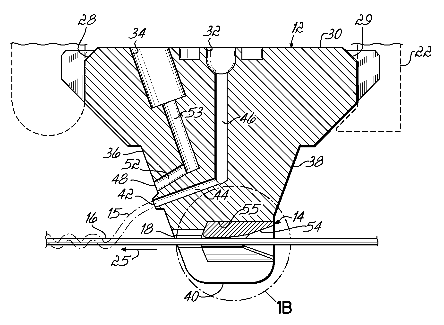
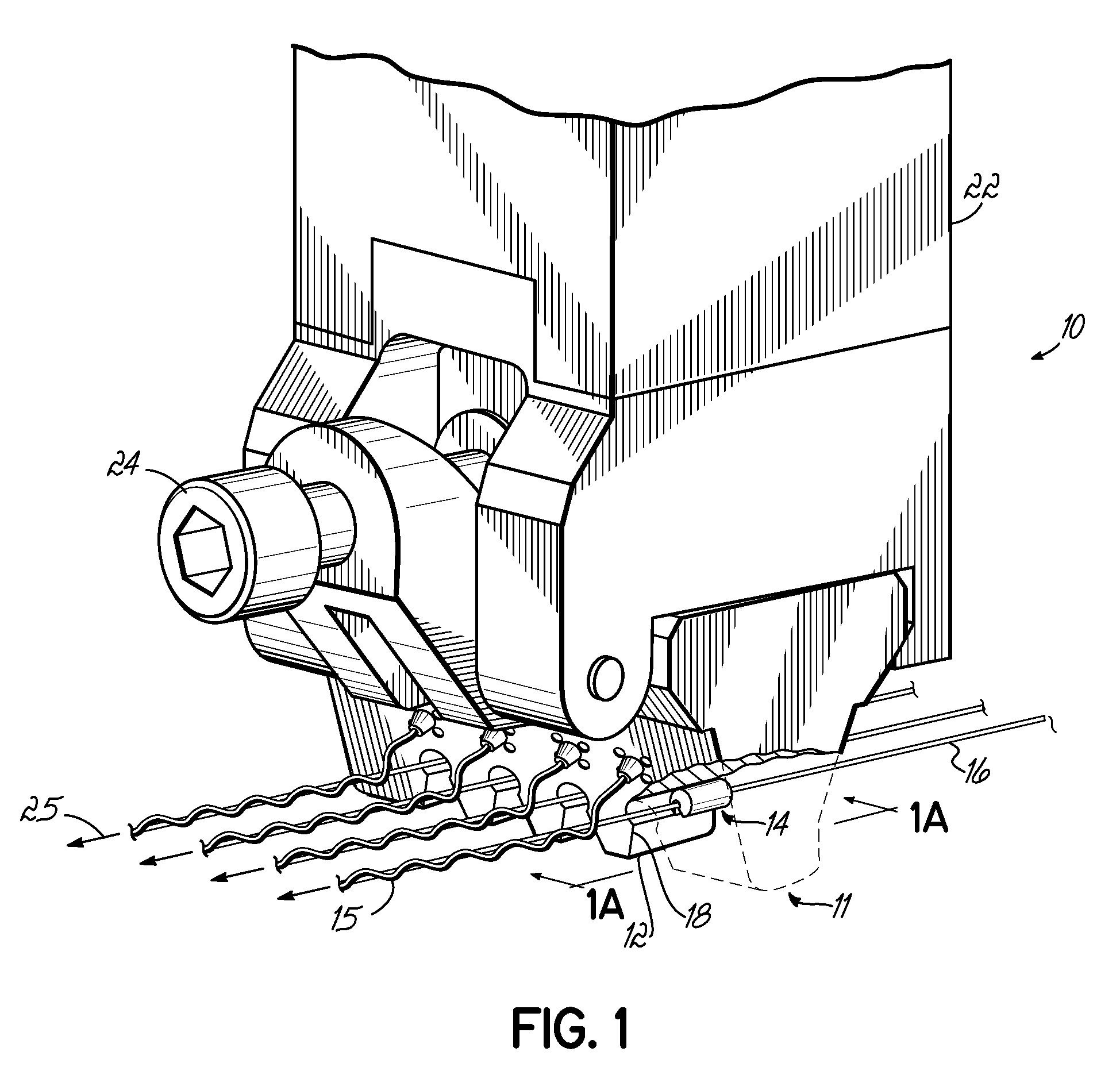
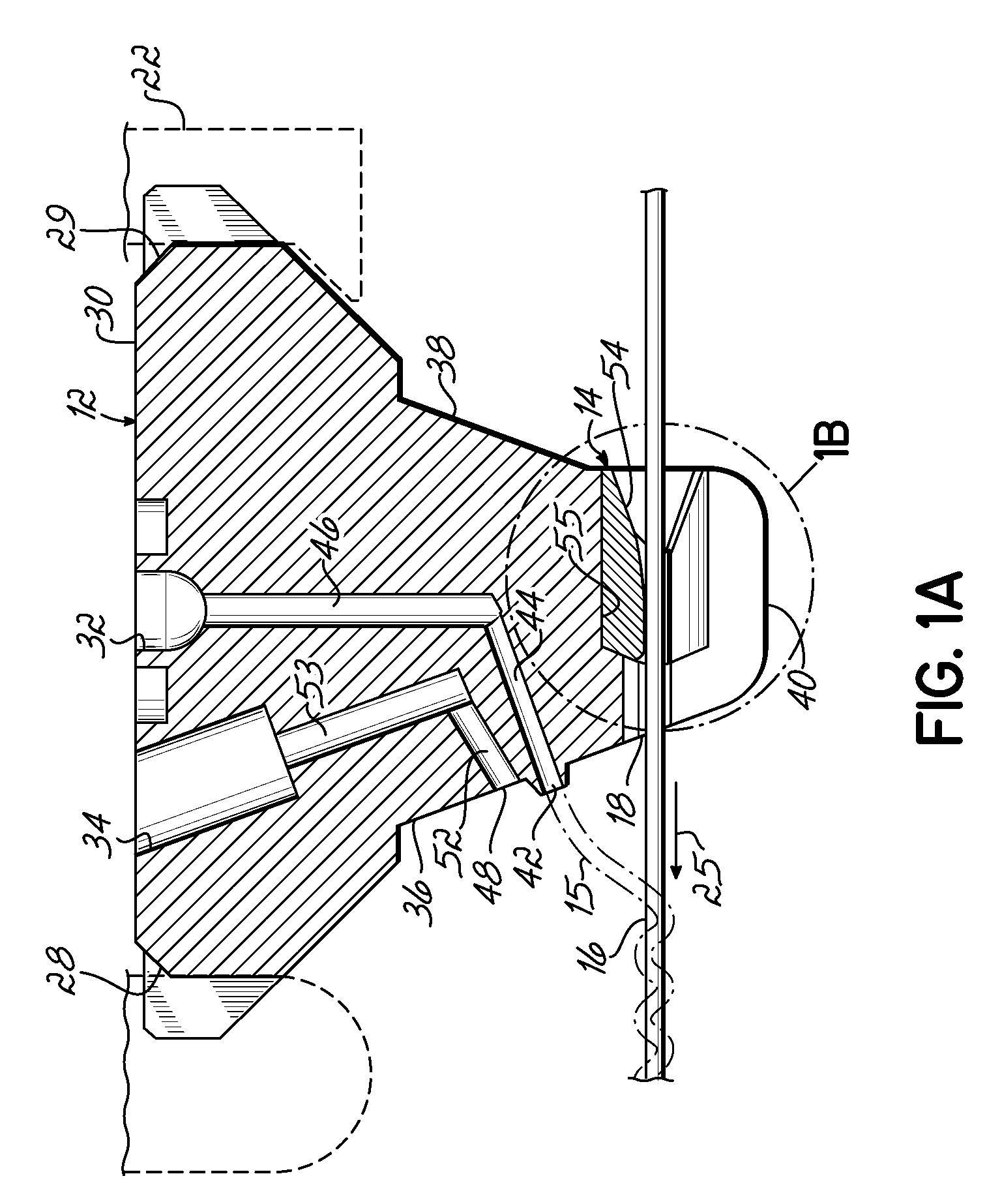
[0028]For the purposes of this description, words of direction such as “upward”, “vertical”, “horizontal”, “right”, “left”, “front”, “rear”, “side”, “top”, “bottom”, and the like are applied in conjunction with the drawings for purposes of clarity and providing a reference frame in the present description only. As is well known, liquid dispensing devices may be oriented in substantially any orientation, so these directional words should not be used to imply any particular absolute directions for an apparatus consistent with the invention.

[0029]Referring to FIGS. 1, 1A, 2, 3, and 4, a representative dispensing module 10 is coupled with a nozzle assembly 11, which includes a nozzle 12 and a plurality of protective members 14 constructed in accordance with an embodiment of the invention. The dispensing module 10 is configured to dispense liquid filaments 15 from the nozzle assembly 11 onto strands 16 of material, which are fed and move in a machine direction (as indicated by the single...


PUM

PropertyMeasurementUnit
diametersaaaaaaaaaa
thickaaaaaaaaaa
thickaaaaaaaaaa

Abstract

A protective member (14) and a nozzle assembly (11) incorporating the protective member (14) are provided. The protective member (14) is for use with a nozzle (12) having a strand guide passageway (18) for receiving a strand (16) of material. Protective member (14) comprises a body (60) configured to be received in the strand guide passageway (18) of the nozzle (12). The body (60) of the protective member (14) has a passageway (63) for the strand (16) and is disposed between the strand guide passageway (18) and the moving strand (16). The body (60) of the protective member (14) is composed, at least in part, of a material having a wear resistance sufficient to resist wear caused by the strand (16) being guided thereby. Alternatively, a portion of the body (60) may be coated with a material having a wear resistance sufficient to resist wear caused by the strand (16).

Description

CROSS-REFERENCE TO RELATED APPLICATIONS[0001]This application claims the benefit of U.S. Provisional Application No. 60 / 909,817, filed Apr. 3, 2007 (pending), which is hereby incorporated by reference herein in its entirety.TECHNICAL FIELD[0002]The present invention relates generally to liquid dispensing systems, and more specifically, to nozzle assemblies for a liquid dispensing apparatus configured to dispense a liquid filament on a strand of material.BACKGROUND[0003]Many reasons exist for dispensing liquid adhesives, such as hot melt adhesives, in the form of a thin filament with a controlled pattern. One technology capable of dispensing controlled patterns of thin filaments is known as controlled fiberization (for example, CF® technology from Nordson Corporation). CF® technology is especially useful for accurately covering a wider region of a substrate with adhesive dispensed as single filaments or as multiple side-by-side filaments from nozzle passages having small diameters, s...

Claims


Application Information

Patent Timeline
Patent Type & Authority Applications(United States)
IPC IPC(8): B29C47/02
CPCB05B7/0861B05C5/0241Y10T156/1798B65H57/24B65H2701/31B65H57/12B05C5/027
Inventor SAINE, JOEL E.SCHMIDT, PAUL
Owner NORDSON CORP
Why Eureka
Try Eureka