Cable connector

a technology of cable connectors and connectors, applied in the direction of coupling device connection, coupling parts engagement/disengagement, electrical apparatus, etc., can solve the problem of reducing the characteristic impedance with respect to a predetermined reference impedance, and achieve the effect of suppressing the reduction of the characteristic impedan

Inactive Publication Date: 2010-02-04
YAMAICHI ELECTRONICS
View PDF49 Cites 4 Cited by
  • Summary
  • Abstract
  • Description
  • Claims
  • Application Information

AI Technical Summary

Benefits of technology

[0014]In case the contact terminals are configured such that stopper portions in response to stubs of a transmission circuit among the stopper portions and the movable portions of the terminals will be completely excluded from the connecting portions as described above in order to suppress a reduction in characteristic impedance with respect to a predetermined reference impedance value, when an end of a cable is connected to the cable connector, since the actuator member is supported at only the two ends thereof, the actuat

Problems solved by technology

When the cable connector is provided in a transmission path for transmitting differential signals in a relatively high frequency band, e.g., signals at a c

Method used


Image

  • Cable connector
  • Cable connector
  • Cable connector

Examples


Embodiment Construction

[0032]Each of FIGS. 3 and 4 shows an appearance of an embodiment of a cable connector according to the present invention.

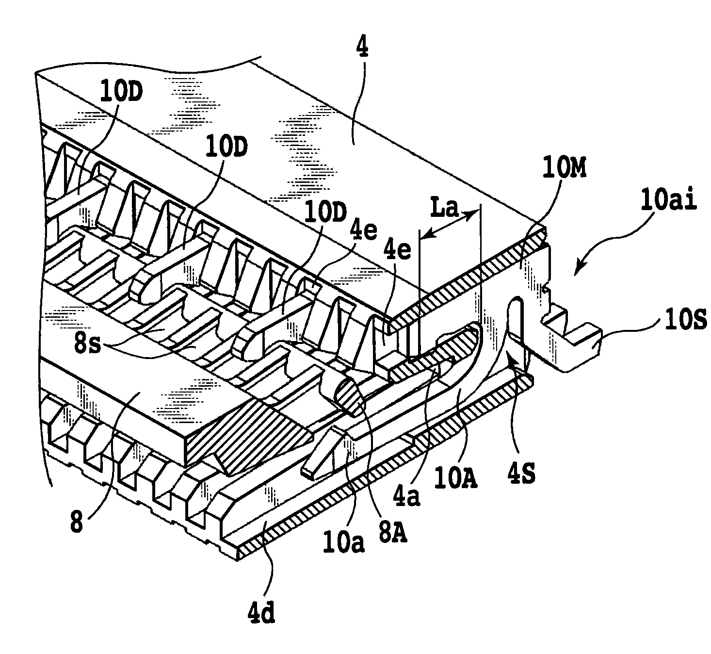
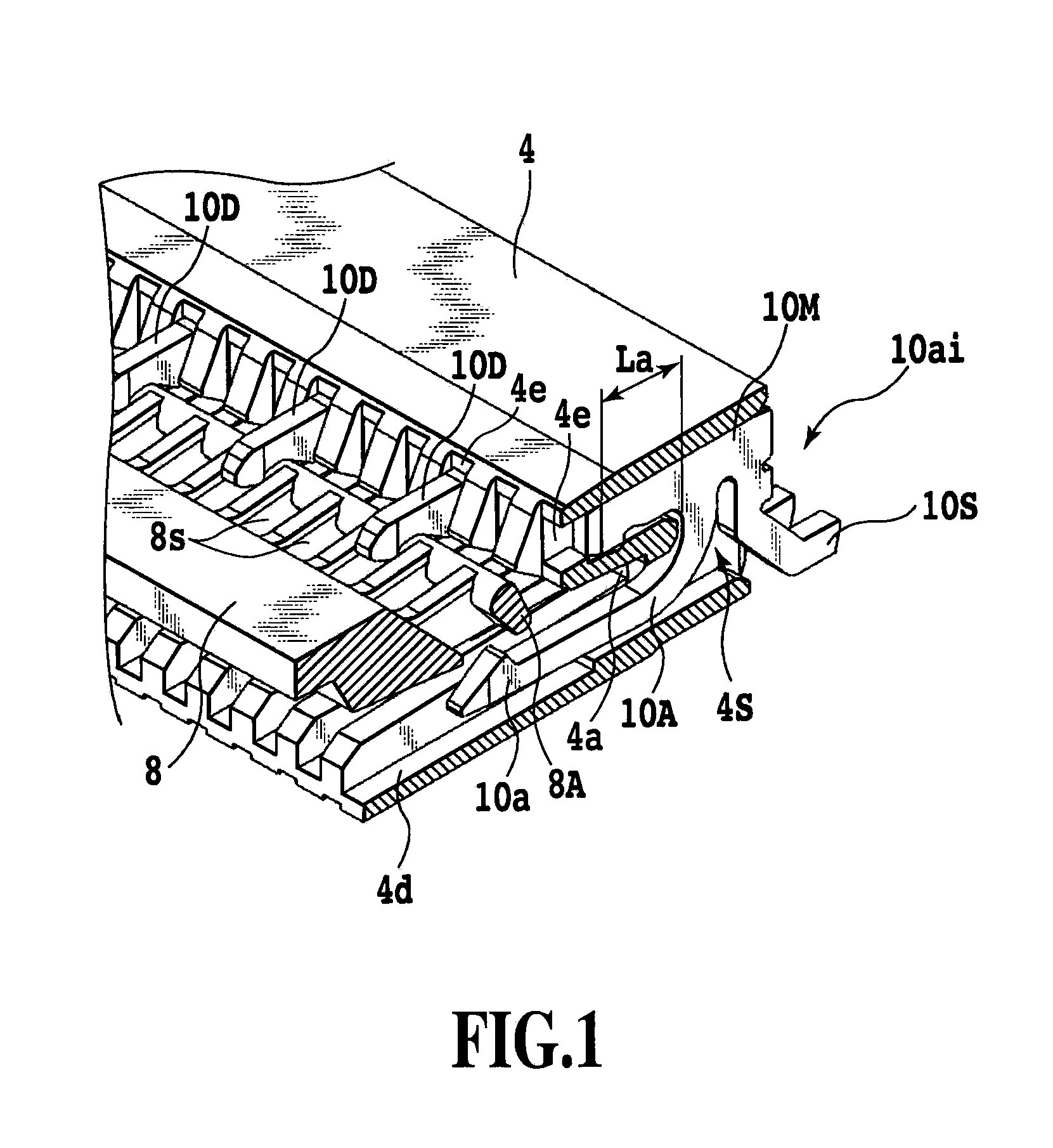
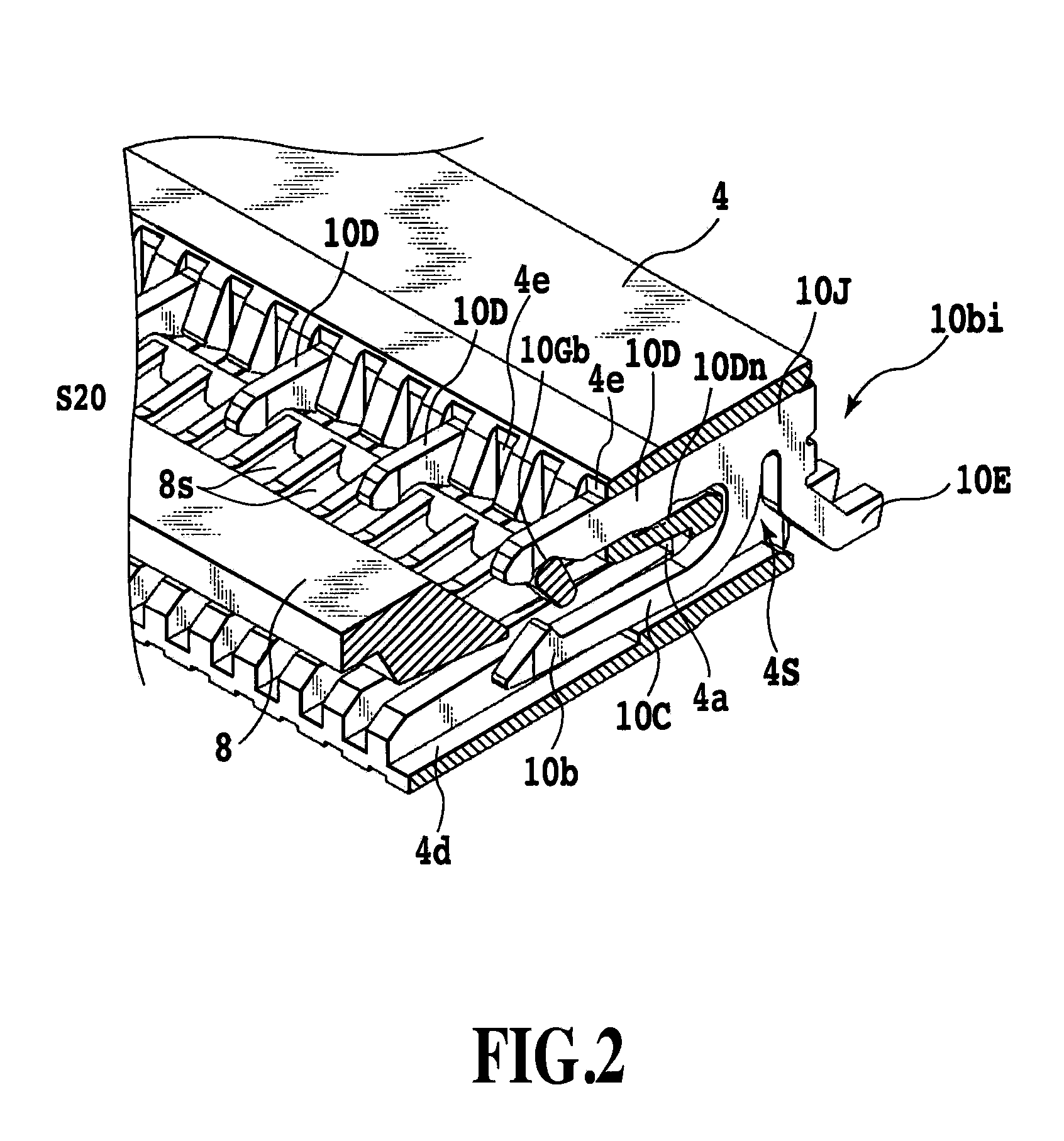
[0033]Referring to FIG. 3, the cable connector is a rotary type connector including a connector main body 4 which is disposed on a printed wiring board 2 and which has a cable housing section 4A (see FIG. 6A), a plurality of contact terminals 10ai and 10bi (i=1 to n where n is a positive integer: see FIGS. 1 and 2) which are provided in the cable housing section 4A of the connector main body 4 and which electrically connect electrode portions of the printed wiring board 2 to electrode portions of a terminal part of a flexible printed circuit 6 to be described later serving as a cable (see FIG. 6A), and an actuator member 8 which is rotational movably supported on two sidewalls 4WR and 4WL of the connector main body 4 and which secures the terminal part of the flexible printed circuit 6 to contact parts of the contact terminals 10ai and 10bi, or releases the termin...


PUM


Abstract

Contact terminals for grounding include a fixing portion for supporting an pressing portion of an actuator member, and contact terminals for signals disposed adjacent to the contact terminals for grounding include a fixing portion shorter than the fixing portion of the contact terminal for grounding. The fixing portion is connected to one end of a movable terminal portion.

Description

[0001]This application claims the benefit of Japanese Patent Application Nos. 2008-195015, filed Jul. 29, 2008, and 2009-074235, filed Mar. 25, 2009, which are hereby incorporated by reference herein in their entirety.BACKGROUND OF THE INVENTION[0002]1. Field of the Invention[0003]The present invention relates to a cable connector for electrically connecting one end of a cable to a wiring board.[0004]2. Description of the Related Art[0005]Cable connectors are made available for electrically connecting electrical components in an electronic apparatus to each other. For example, a cable connector electrically connects an electrical component to a printed wiring board through a flexible flat cable (FFC) or a flexible printed circuit (FPC). Cable connectors employing different cable fixing methods, e.g., rotary-type and slide-type connectors, are used in practice.[0006]For example, as described in Japanese Patent Laid-Open No. 2007-042608, a rotary-type cable connector includes a connec...

Claims


Application Information

Patent Timeline
IPC IPC(8): H01R13/62
CPCH01R12/57H01R12/88H01R12/79H01R12/774
Inventor TAKAHIRA, HIROSHIKIMOTO, TOSHIYA
Owner YAMAICHI ELECTRONICS
Why Eureka
Try Eureka