
Power output apparatus, hybrid vehicle provided with the same, and control method of power output apparatus

a technology of power output apparatus and hybrid vehicle, which is applied in the direction of digital transmission, propulsion using engine-driven generators, electric devices, etc., can solve the problem that the document does not specifically disclose the operation of the motor to output power only by the motor, and achieve the effect of efficient transmission

Inactive Publication Date: 2010-02-04
TOYOTA JIDOSHA KK
View PDF20 Cites 68 Cited by
  • Summary
  • Abstract
  • Description
  • Claims
  • Application Information

AI Technical Summary

Benefits of technology

[0006]The present invention has an object to provide a power output apparatus which can transmit power outputted from a motor efficiently to a drive shaft with change in a change speed state of a transmission mechanism, a hybrid vehicle provided with the same, and a control method of the power output apparatus.
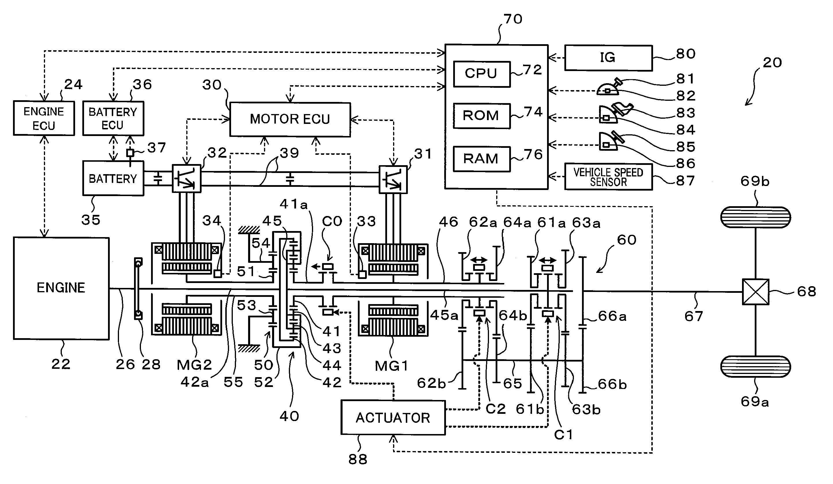
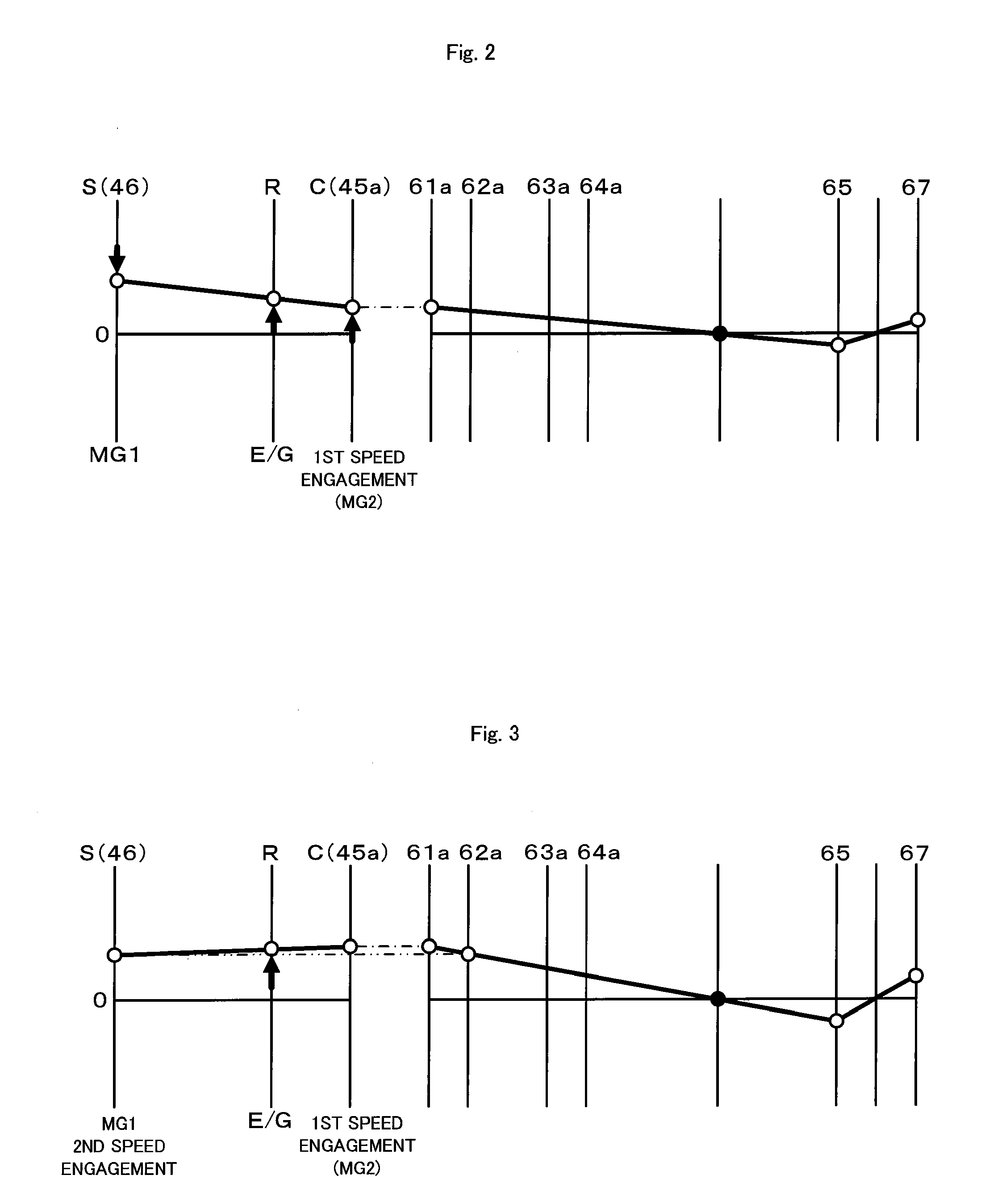
[0009]The power output apparatus can transmit power from either of the first and the second motors to the drive shaft with a change speed at a predetermined speed ratio by the transmission mechanism when the internal combustion engine is stopped while the driving source-element connection is made and only one of the first and second motors is connected to the drive shaft by the transmission mechanism. In this state, if the connection between one of the first and second motors and the drive shaft is disconnected and only the other of the first and second motors is connected to the drive shaft by the transmission mechanism so as to output the power, the power from the other of the first and second motors can be transmitted to the drive shaft by the transmission mechanism at a predetermined speed ratio. In the power output apparatus, if the change speed state of the transmission mechanism is changed and the power from the other of the first and second motors is to be transmitted to the drive shaft when the power from one of the first and second motors is being transmitted to the drive shaft while the driving source-element connection is made as above, first, the driving source-element connection by the connecting / disconnecting unit is disconnected. Then the rotation speed adjusting process in which the rotation speed of the other of the first and second motors is adjusted so that the other of the first and second motors can be connected to the drive shaft and the power transfer process for transferring the power from the one to the other of the first and second motors while both the first and second motors are connected to the drive shaft by the transmission mechanism are executed while the driving source-element connection is disconnected and the power based on the set power demand is outputted to the drive shaft, and the connection between one of the first and second motors and the drive shaft by the transmission mechanism is disconnected. By this operation, the other of the first and second motors is connected to the drive shaft, and the power from the other of the first and second motors can be transmitted to the drive shaft with the change speed by the transmission mechanism. As a result, in the power output apparatus, the power outputted from the first and the second motors can be efficiently transmitted to the drive shaft with change in the change speed state of the transmission mechanism.
[0018]In the hybrid vehicle, the power outputted from the motor is speed-changed by the transmission mechanism so that the power demand can be efficiently transmitted to the drive shaft, thereby improving fuel consumption and running performance of the hybrid vehicle.
[0020]According to the control method of the power output apparatus, the power outputted from the first or second motor can be efficiently transmitted to the drive shaft with change in the change speed state of the transmission mechanism.

Problems solved by technology

However, either of the Patent Documents does not specifically disclose how motor operation to output power only by the motor is carried out at all.

Method used


Image

  • Power output apparatus, hybrid vehicle provided with the same, and control method of power output apparatus
  • Power output apparatus, hybrid vehicle provided with the same, and control method of power output apparatus
  • Power output apparatus, hybrid vehicle provided with the same, and control method of power output apparatus

Examples


Embodiment Construction

[0045]Next, a best mode for carrying out the present invention will be described using an embodiment.

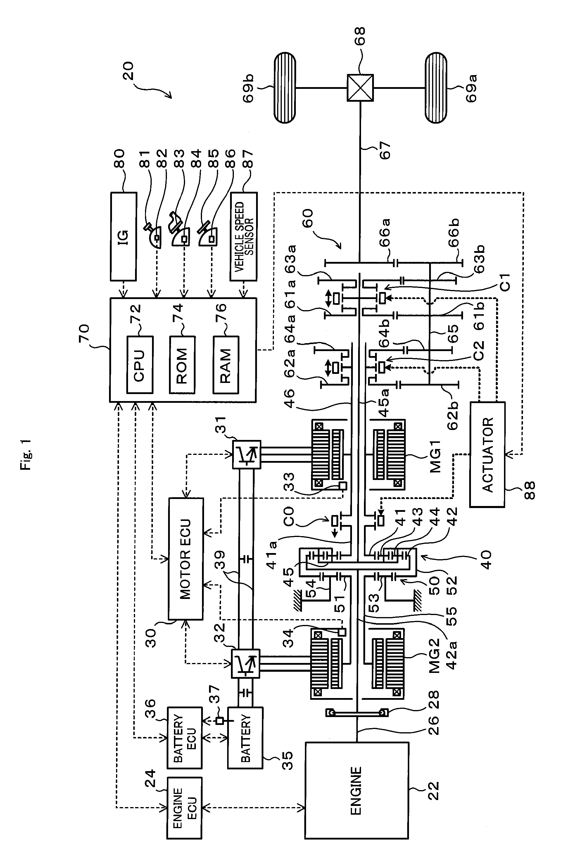
[0046]FIG. 1 is a schematic block diagram of a hybrid vehicle 20 according to the embodiment of the present invention. The hybrid vehicle 20 shown in the figure is constructed as a rear drive vehicle and is provided with an engine 22 arranged in the front of the vehicle, a power distribution and integration mechanism (differential rotating mechanism) 40 connected to a crankshaft 26, which is an output shaft of the engine 22, a motor MG1 connected to the power distribution and integration mechanism 40 and capable of power generation, a motor MG2 arranged coaxially with the motor MG1 and connected to the power distribution and integration mechanism 40 through a reduction gear mechanism 50, capable of power generation, a transmission 60 that can transmit power from the power distribution and integration mechanism 40 to a drive shaft 67 with change in a speed ratio, a hybrid electronic c...


PUM


Abstract

In a hybrid vehicle, in order to stop an engine while a clutch is kept engaged and to transmit power from a motor to a drive shaft by changing a change speed state of a transmission when the power from a second motor is being transmitted to the drive shaft by the transmission, for example, a rotation speed of the first motor is adjusted so that the first motor can be connected to the drive shaft with the clutch disengaged while torque commands for both motors are set so that the power based on torque demand is outputted to the drive shaft, the power is transferred from the second motor to the first motor while both motors are connected to the drive shaft by the transmission, and the connection between the second motor and the drive shaft by the transmission is disconnected.

Description

TECHNICAL FIELD[0001]The present invention relates to a power output apparatus, hybrid vehicle provided with the same, and control method of power output apparatus.BACKGROUND ART[0002]A power output apparatus provided with an internal combustion engine, two motors, a so-called Ravigneaux-type planetary gear mechanism, and a parallel-shaft type transmission which can selectively connect two output elements of the planetary gear mechanism to an output shaft has been known as this type of power output apparatus (See Patent Document 1, for example). The power output apparatus is intended for a front-wheel-drive vehicle, and in the power output apparatus, the internal combustion engine is arranged laterally, and rotating shafts of the internal combustion engine and the planetary gear mechanism as well as the two motors and the parallel-shaft type transmission are extended in parallel with each other. Also, those including a planetary gear device including an input element connected to th...

Claims


Application Information

Patent Timeline
IPC IPC(8): B60W10/04B60K6/442F16H3/44B60W20/00H04L27/227B60L50/16H04B1/66H04L27/22
CPCB60K6/36Y10T477/26B60K6/547B60L2240/423B60L2240/486B60W10/02B60W10/08B60W10/11B60W10/113B60W20/00B60W2540/10B60W2710/083B60W2710/105F16H3/006F16H3/728F16H2037/0873F16H2200/0043F16H2200/2005F16H2200/2007F16H2200/2043F16H2200/2064F16H2200/2097Y02T10/6239Y02T10/642B60L11/123B60L11/14B60L11/1861B60L15/20B60L2210/40B60L2220/14B60L2240/12B60L2240/421B60L2240/429B60L2240/441B60L2240/443B60L2240/545B60L2240/547B60L2240/549B60L2240/80B60L2250/24B60L2250/26B60L2260/26B60L2270/145B60K6/445B60L50/61B60L50/16B60L58/12Y02T10/62Y02T10/64Y02T10/70Y02T10/7072Y02T10/72B60K2006/4833B60K6/48B60W2510/081B60W10/06B60W20/40
Inventor KATSUTA, HIROSHIOBA, HIDEHIRO
Owner TOYOTA JIDOSHA KK
Learn More