Large surface area temperature sensing device

a temperature sensing device and large surface area technology, applied in the field of large surface area temperature sensing devices, can solve the problems of large heat generation, adversely affecting tissues or organs adjacent to treated tissue or organs, and damage to the esophagus

Active Publication Date: 2010-02-04
CIRCA SCI
View PDF27 Cites 63 Cited by
  • Summary
  • Abstract
  • Description
  • Claims
  • Application Information

AI Technical Summary

Benefits of technology

[0016]In a specific embodiment, the method of the present invention may be effected during left atrial ablation, which is a surgical procedure that may be used to treat atrial fibrillation. During a left atrial ablation procedure, temperature may be monitored at a plurality of locations spaced over an area of an interior surface of a front portion of a subject's esophageal wall that is located adjacent to the left atrium of the subject's heart. Such temperature monitoring may be effected without any substantial change in the

Problems solved by technology

The degree of heating or cooling that is required to optimize the efficiency of some thermal techniques may adversely affect tissues or organs that are adjacent to a treated tissue or organ.
For example, a great deal of heat is generated when left atrium ablation techniques are used to treat atrial fibrillation in human subjects.
As a consequence of this intimate arrangement between the esophagus E and the left atrium LA, the heat generated during left atrium ablation may damage the esophagus and may, in some cases, create an esophageal fistula.
Unfortunately, the complications that arise from esophageal fistula often do not present themselves until weeks after the procedure and, in many cases, at too late a time to treat and/or cure the sometimes fatal damage that has been don

Method used


Image

  • Large surface area temperature sensing device
  • Large surface area temperature sensing device
  • Large surface area temperature sensing device

Examples


Embodiment Construction

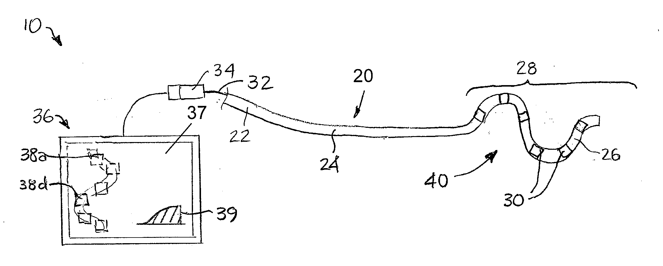
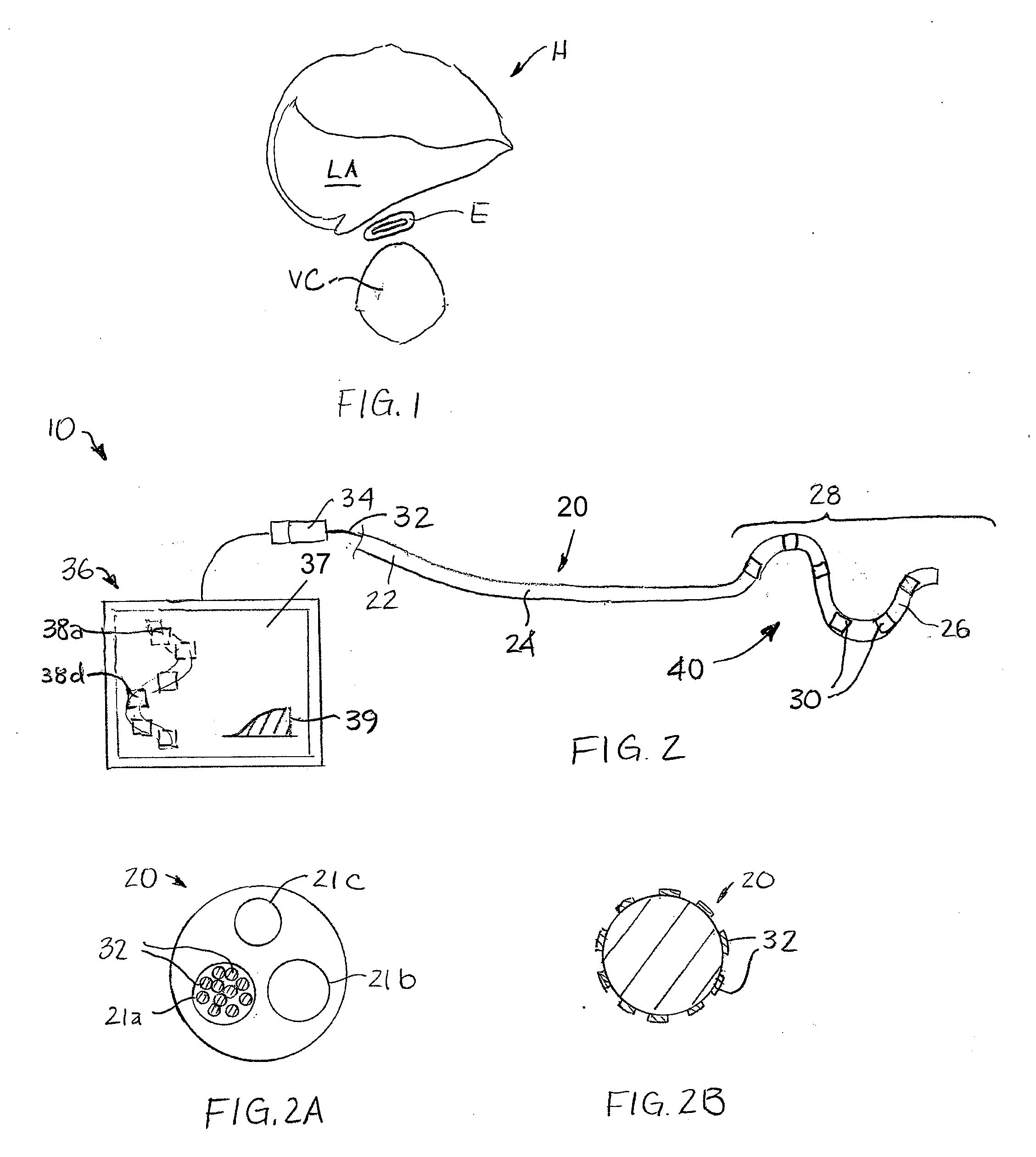
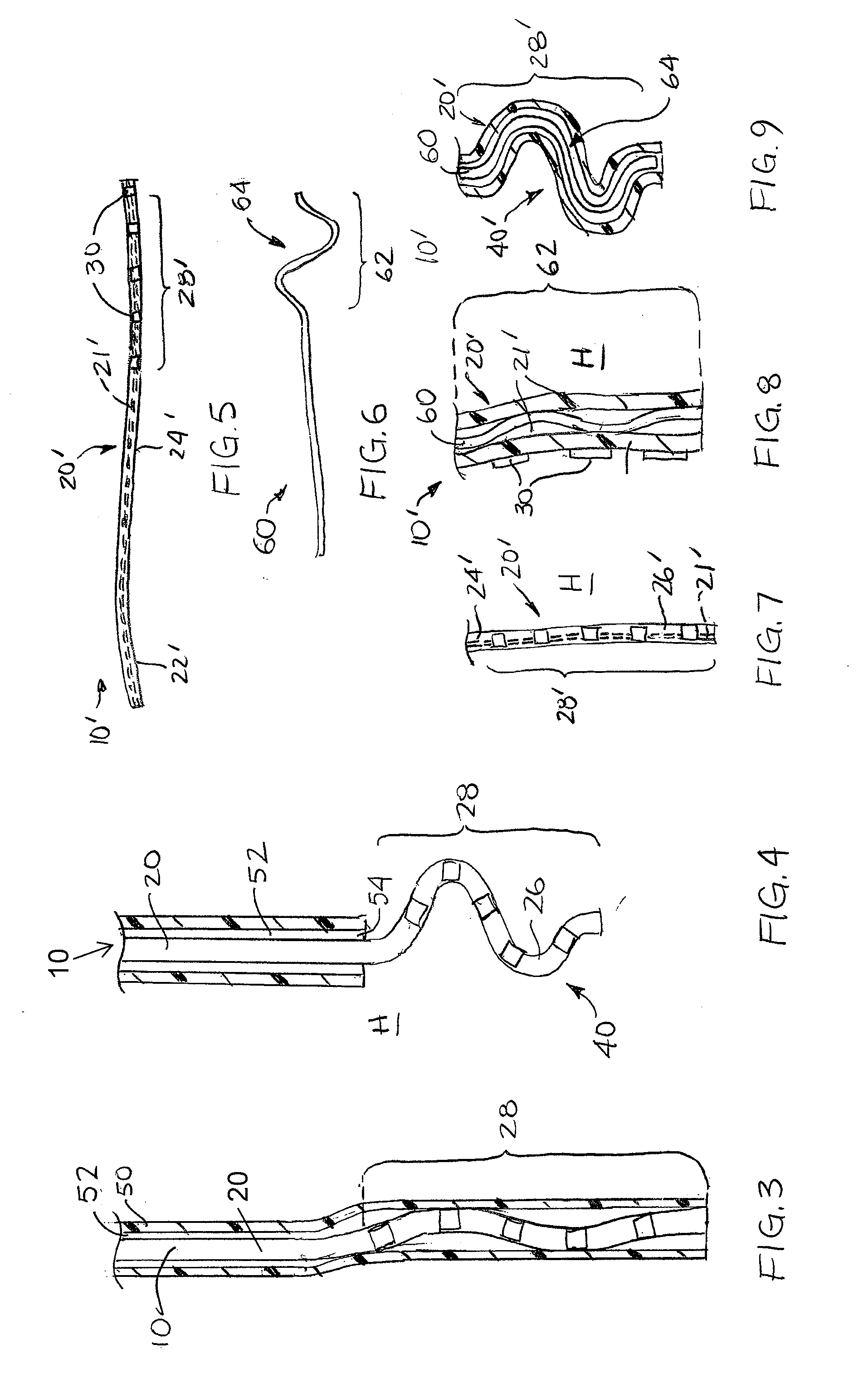
[0034]As shown in FIG. 2, a temperature probe 10 according to an embodiment of the present invention includes an elongate member 20 with a proximal portion 22, an intermediate portion 24, and a distal portion 26. In addition, temperature probe 10 includes a plurality of temperature sensors 30 located along one or both of intermediate portion 24 and distal portion 26. More specifically, temperature sensors 30 are positioned along a section 28 of elongate member 20 that is configured to have a substantially two-dimensional arrangement 40 when placed adjacent to or against an area of a surface of a tissue or organ in the body of a subject. Section 28 may also carry other elements, such as radioopaque markers, echogenic markers, other sensors, and the like. The shape of the substantially two-dimensional arrangement 40 distributes three or more temperature sensors 30 over an area (e.g., an area array in the depicted embodiment) that is relatively large when compared with the miniscule ar...


PUM


Abstract

A temperature probe for monitoring temperatures of a surface of a tissue or organ within the body of a subject includes a section with a substantially two-dimensional arrangement and a plurality of temperature sensors positioned across an area defined by the substantially two-dimensional arrangement. Such an apparatus may be used in conjunction with procedures in which thermal techniques are used to diagnose a disease state or treat diseased tissue. Specifically, a temperature probe may be used to monitor temperatures across an area of a surface of a tissue or organ located close to the treated tissue to prevent subjection of the monitored tissue or organ to potentially damaging temperatures.

Description

CROSS-REFERENCE TO RELATED APPLICATION[0001]This application claims the benefit of priority under 35 U.S.C. §119(e) to U.S. Provisional Patent Application Ser. No. 61 / 037,624, filed on Mar. 18, 2008, the entire disclosure of which is, by this reference, hereby incorporated herein.TECHNICAL FIELD[0002]The present invention relates generally to apparatuses for monitoring temperatures of an internal surface of a hollow organ in the body of a subject and, more specifically, to temperature monitoring apparatuses that are configured to monitor temperatures at different locations spread over an area of an internal surface of a hollow organ. The present invention also relates to methods in which temperatures across areas of an internal surface of a hollow organ are monitored, including techniques in which an adjacent tissue or organ is heated or cooled.BACKGROUND OF RELATED ART[0003]A variety of techniques have been developed in which tissues or organs in a patient's body are heated or cool...

Claims


Application Information

Patent Timeline
IPC IPC(8): A61B5/01
CPCA61B5/015A61B5/6853A61B2562/0271A61B5/6859A61B2018/00797A61B5/6858A61B2034/2063A61B34/20A61B2090/376A61B5/4836A61B5/0036A61B5/01A61B5/687A61B5/6873A61B18/00A61B2018/00357A61B2018/00404A61B2018/00529A61B2018/00547A61B2018/00577A61B5/742
Inventor FOJTIK, SHAWN P.
Owner CIRCA SCI
Why Eureka
Try Eureka