Pattern shape predicting method and pattern shape predicting apparatus

a pattern shape and predicting method technology, applied in the field of pattern shape predicting method and pattern shape predicting apparatus, can solve the problems of plurality of directions, inability to predict the shape of a plurality of directions, and inconvenient simulation of the method

Inactive Publication Date: 2010-02-04
KK TOSHIBA
View PDF17 Cites 31 Cited by
  • Summary
  • Abstract
  • Description
  • Claims
  • Application Information

AI Technical Summary

Problems solved by technology

There are various causes of the roughness.
However, in this method, although highly accurate simulation is possible, time required for the simulation is extremely long.
Therefore, the method is not suitable for simulating and evaluating an actual layout in a wide range.
However, in the related art, althou

Method used


Image

  • Pattern shape predicting method and pattern shape predicting apparatus
  • Pattern shape predicting method and pattern shape predicting apparatus
  • Pattern shape predicting method and pattern shape predicting apparatus

Examples


first embodiment

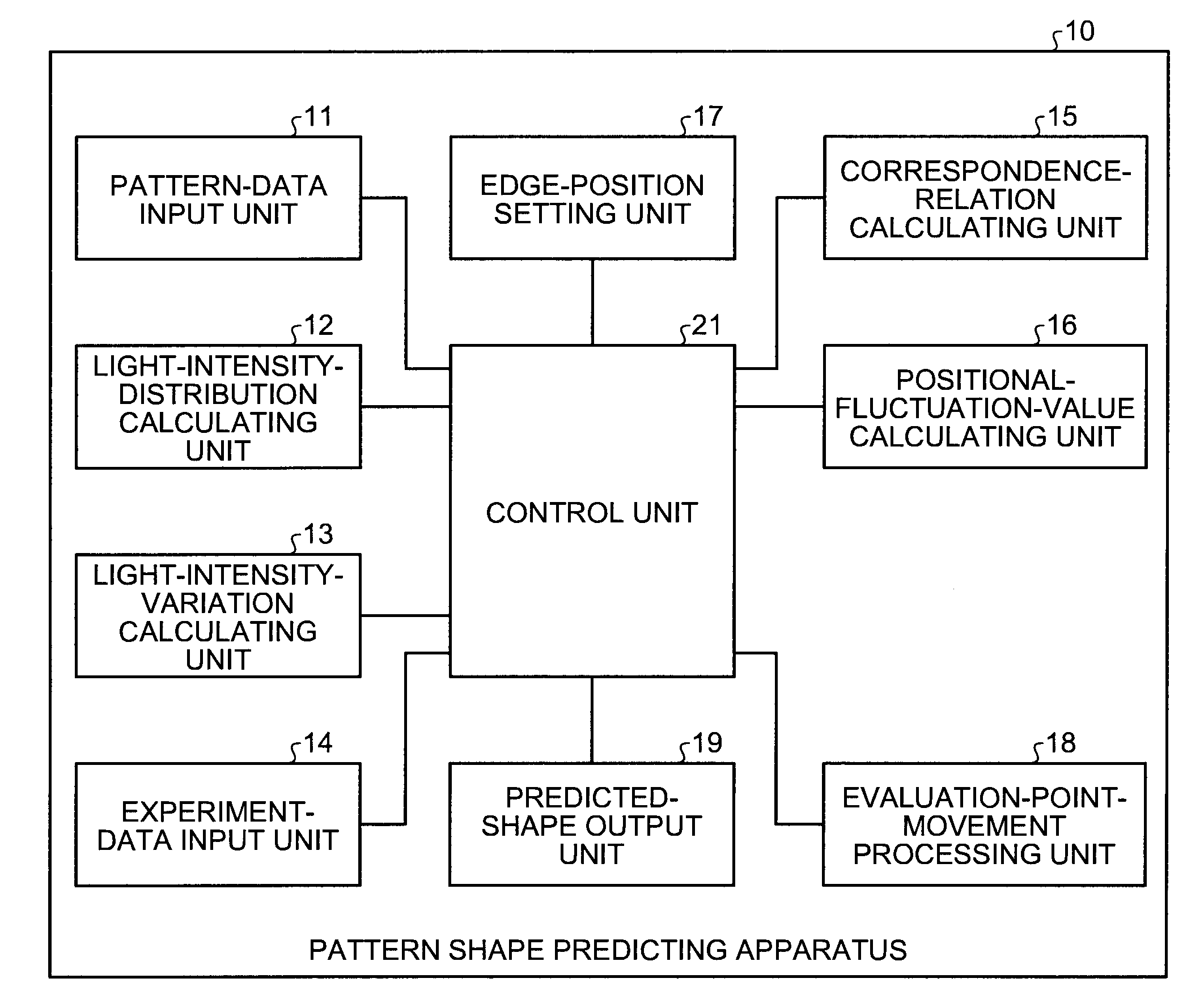
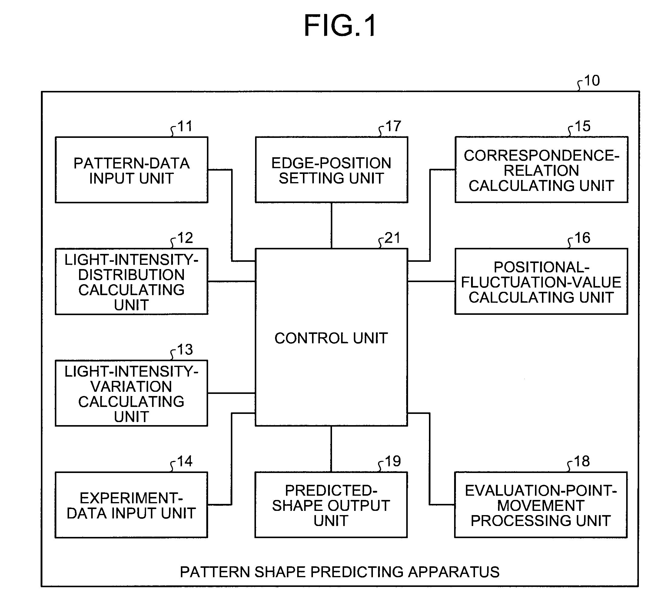
[0032]FIG. 1 is a block diagram of a configuration of a pattern shape predicting apparatus according to the present invention. A pattern shape predicting apparatus 10 is an apparatus that predicts roughness of a pattern formed on a substrate such as a mask or a wafer. The pattern shape predicting apparatus 10 according to this embodiment predicts a pattern shape viewed from an upper side of the substrate. The pattern shape predicting apparatus 10 predicts a pattern shape by predicting a finish position of a pattern edge (an evaluation point) on the pattern. In the explanation of this embodiment, the substrate is a wafer. Therefore, the pattern shape predicting apparatus 10 according to this embodiment predicts a shape of a pattern formed on the wafer when a pattern on the mask is transferred onto the wafer.

[0033]The pattern shape predicting apparatus 10 includes a pattern-data input unit 11, a light-intensity-distribution calculating unit 12, a light-intensity-variation calculating ...

second embodiment

[0101]In the present invention, a representative evaluation point is set out of a plurality of evaluation points continuously adjacent to one another and the standard deviation σ2 of a finish position at this evaluation point is calculated.

[0102]In the second embodiment, shape prediction for a pattern is performed by using the pattern shape prediction apparatus 10 having a configuration same as that in the first embodiment. Therefore, explanation of the configuration of the pattern shape predicting apparatus 10 is omitted.

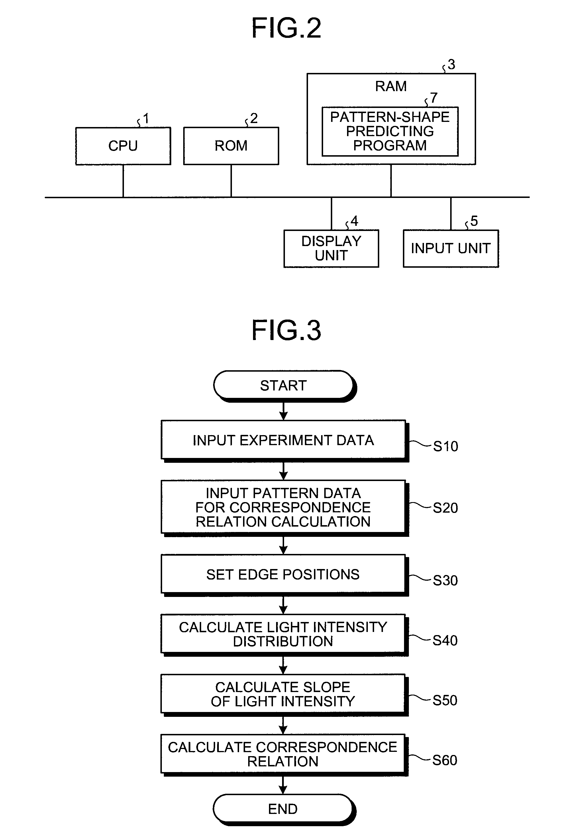
[0103]A processing procedure for calculating correspondence relation information according to the second embodiment is the same as the processing procedure for calculating correspondence information according to the first embodiment explained with reference to FIG. 3. Therefore, explanation of the processing procedure is omitted. A processing procedure for predicting a pattern shape according to the second embodiment is explained below. Explanation of a procedure f...


PUM


Abstract

A pattern shape predicting method comprising: predicting, with simulation, an intensity distribution of a pattern image concerning a pattern shape of a pattern on substrate formed on a substrate based on pattern data; calculating a first pattern edge position from the intensity distribution of the pattern image; calculating a feature value of the intensity distribution of the pattern image in a predetermined range including the first pattern edge position; calculating a fluctuation amount of the first pattern edge position from the feature value using a correlation; and predicting a second pattern edge position taking into account the fluctuation amount with respect to the first pattern edge position.

Description

CROSS-REFERENCE TO RELATED APPLICATIONS[0001]This application is based upon and claims the benefit of priority from the prior Japanese Patent Application No. 2008-196428, filed on Jul. 30, 2008; the entire contents of which are incorporated herein by reference.BACKGROUND OF THE INVENTION[0002]1. Field of the Invention[0003]The present invention relates to a pattern shape predicting method and a pattern shape predicting apparatus.[0004]2. Description of the Related Art[0005]In recent years, according to a reduction in size of semiconductor devices, line edge roughness (hereinafter, “roughness”) of patterns formed on masks and wafers becomes conspicuous. Fluctuation in dimensions of the patterns due to the roughness substantially affects device characteristics.[0006]There are various causes of the roughness. It is known that, as described in SPIE Vol. 6519 651941 “Some Non-resist Component Contributions to LER and LWR in 193 nm Lithography”, a resist material, resist thickness, contra...

Claims


Application Information

Patent Timeline
IPC IPC(8): G06F17/50G03F1/36G03F1/68G03F1/70H01L21/027
CPCG03F1/36G03F1/144G03F1/68
Inventor UNO, TAIGAKOTANI, TOSHIYA
Owner KK TOSHIBA
Why Eureka
Try Eureka