Blending System

Inactive Publication Date: 2010-02-11
TECHNI BLEND
View PDF32 Cites 36 Cited by
  • Summary
  • Abstract
  • Description
  • Claims
  • Application Information

AI Technical Summary

Benefits of technology

[0004]Additionally, conventional blending systems, especially those used to blend syrup and water, typically have a storage tank that holds chilled carbonated mixed fluid for subsequent delivery to a filler system that fills individual containers with the mixed fluid. The addition of the storage tank greatly increases the overall size of the blending system and the storage tank must be regularly cleaned. Thus, a blending system setup without such a holding tank would be advantageously smalle

Problems solved by technology

While a system such as this is functio

Method used


Image

  • Blending System
  • Blending System
  • Blending System

Examples


Embodiment Construction

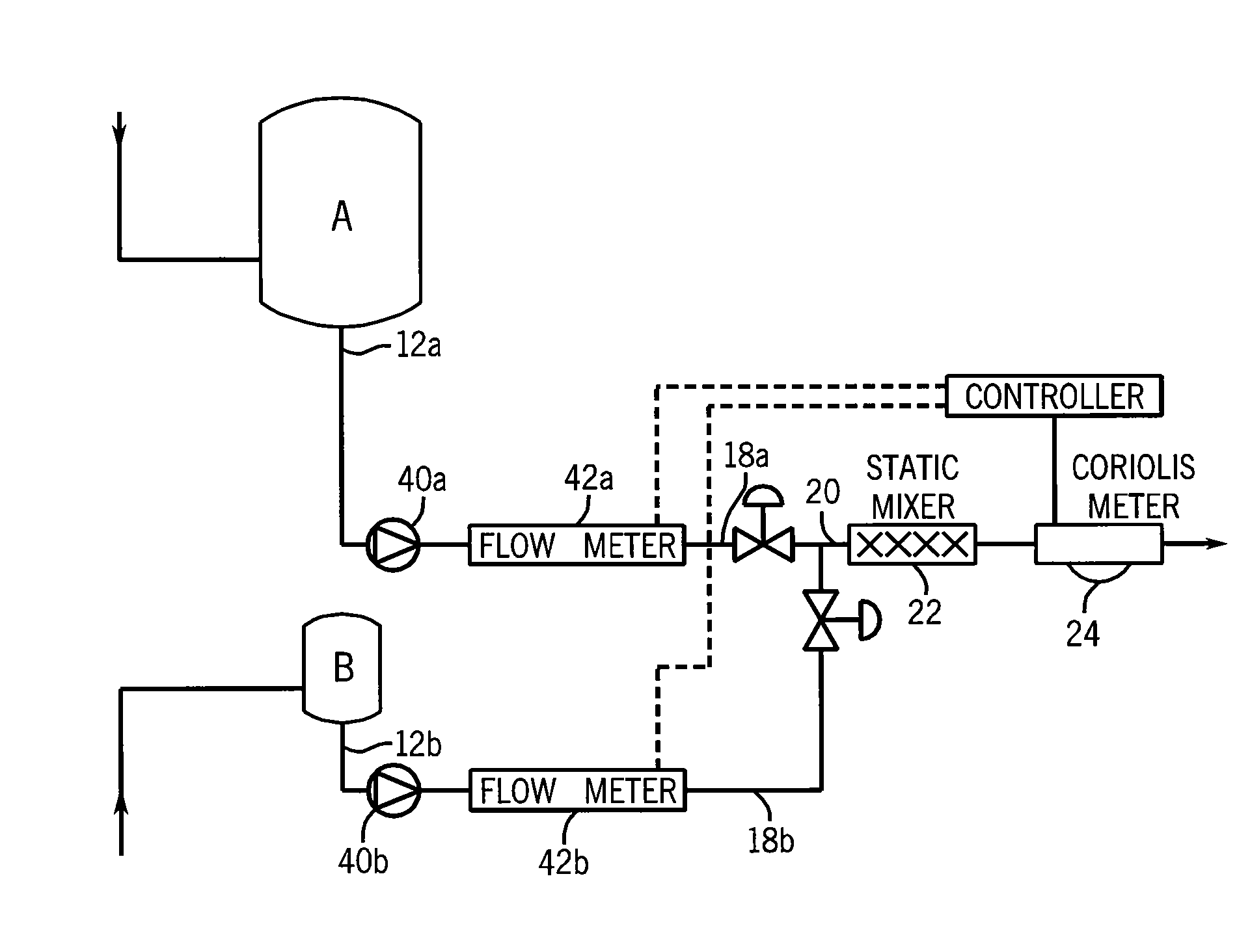
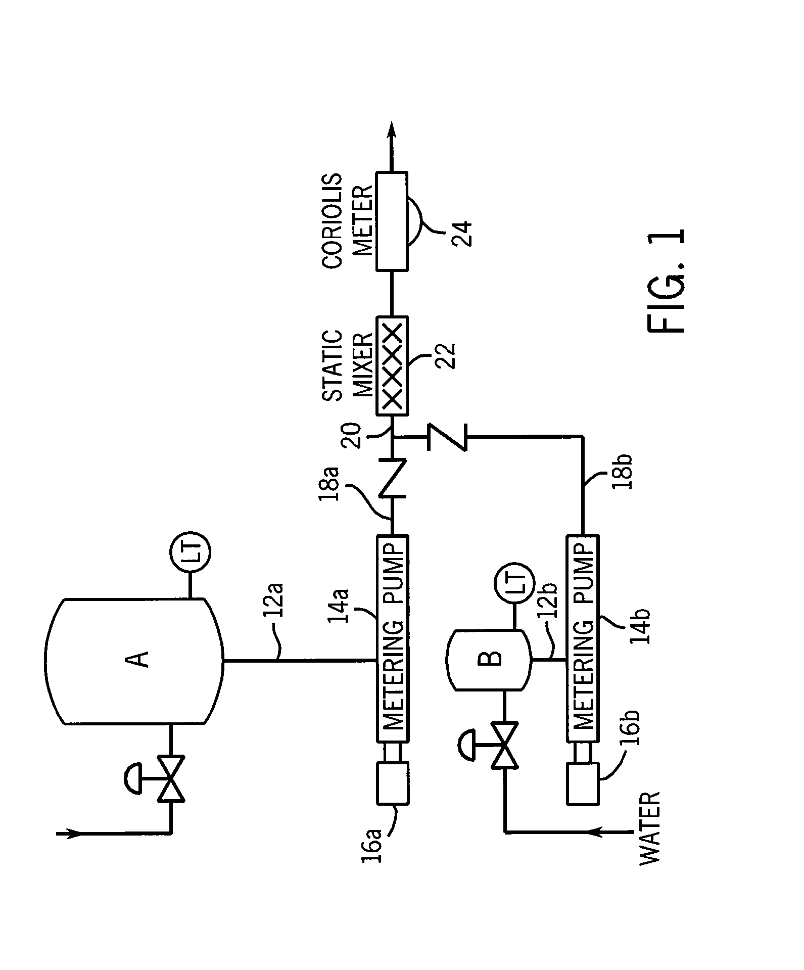
[0016]FIG. 1 provides a general illustration of the present invention, which can be used in a variety of applications. As shown in FIG. 1, a first liquid component is supplied from a source A, which may be a tank or reservoir (or alternatively may simply be a pipe that supplies the liquid component), and a second liquid component is supplied from a source B, which again may be a tank or reservoir (or alternatively may simply be a pipe that supplies the liquid component). The two liquid components are destined to be mixed or blended together to form a final, blended product.

[0017]From source A, the first liquid component is supplied through a line 12a to a metering pump 14a, which is driven by a motor 16a. Similarly, the second liquid component is supplied through a line 12b to a metering pump 14b, which is driven by a motor 16b. The metering pumps 14a, 14b function to accurately dispense desired quantities of the first and second liquid components according to a predetermined ratio....


PUM

PropertyMeasurementUnit
Pressureaaaaaaaaaa
Flow rateaaaaaaaaaa
Densityaaaaaaaaaa

Abstract

A blending system includes a first liquid supply arrangement for providing a first liquid component, a second liquid supply arrangement for providing a second liquid component, a mixing arrangement for mixing the first and the second liquid components to form a blending liquid, and a mass flow measuring device for determining the mass flow of the blended liquid at a location downstream of the mixing arrangement. The blending system further includes a control arrangement for controlling the first and the second liquid supply arrangements in response to the mass flow measuring device. The mass flow measuring device may also measure the density and/or volumetric flow of the mixed liquid. The blending system may also be setup without a holding tank.

Description

CROSS-REFERENCE TO RELATED APPLICATION[0001]The present application claims the benefit of U.S. Ser. No. 61 / 086,360, filed Aug. 5, 2008.BACKGROUND AND SUMMARY OF THE INVENTION[0002]This invention relates generally to liquid blending and, more particularly, to a liquid blending system that provides precisely controlled dispensing of the liquid components to attain a blended liquid having desired characteristics.[0003]In fluid blending systems, such as are used in the food and beverage industry, it has been known to route the flow of each liquid component through a mass flow meter in order to blend the components together in a desired ratio. The ratio of the final, blended product is then tested in an out-of-line sampling process at a location far downstream of the location at which the blending operation takes place. While a system such as this is functional, it is subject to error and waste. For example, if the ratio of the final, blended product is outside of specifications, this wi...

Claims


Application Information

Patent Timeline
IPC IPC(8): A47J31/00G05D11/02B01F5/04B01F3/04
CPCB01F3/04815B01F3/0861B01F3/088G05D11/137B01F15/0429B01F2003/049B01F5/0602B01F23/2363B01F23/237621B01F23/45B01F23/49B01F25/42B01F35/833
Inventor KEMP, DAVID M.
Owner TECHNI BLEND
Why Eureka
Try Eureka