Linear synchronous motor

Inactive Publication Date: 2010-02-11
SANYO DENKI CO LTD
View PDF3 Cites 13 Cited by
  • Summary
  • Abstract
  • Description
  • Claims
  • Application Information

AI Technical Summary

Benefits of technology

[0006]An object of the present invention is to provide a linear synchronous motor in which the manufacturing cost of a stator used therein can be reduced, and magnetic loss and iron loss can also be reduced.
[0007]Another object of the present invention is to provide a linear synchronous motor in which the configuration of a yoke used therein can be simplified.
[0008]Still another object of the present invention is to provide a linear synchronous motor in which a lubricant can readily be supplied to a linear bearing that supports a mover so as to allow the mover to reciprocate relative to the stator.

Problems solved by technology

Conventional linear synchronous motors have issues of high manufacturing cost of the stator and high magnetic loss.
However, the configuration of the yoke which magnetically connects the stator core divided bodies will inevitably be complicated.

Method used


Image

  • Linear synchronous motor
  • Linear synchronous motor
  • Linear synchronous motor

Examples


Embodiment Construction

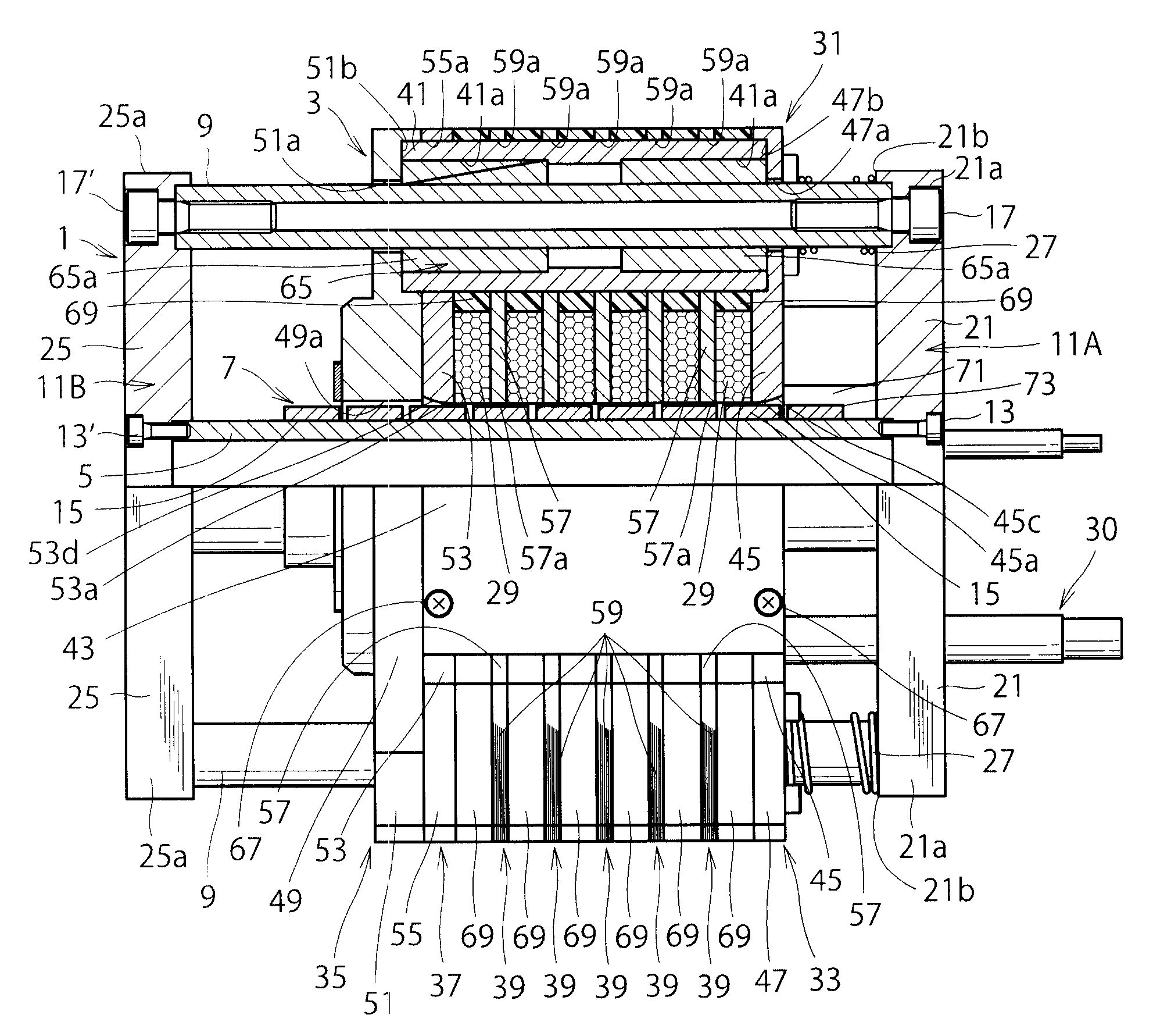
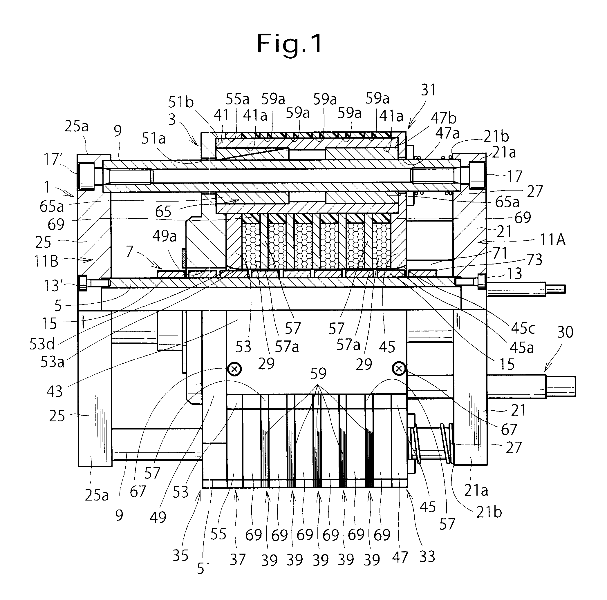
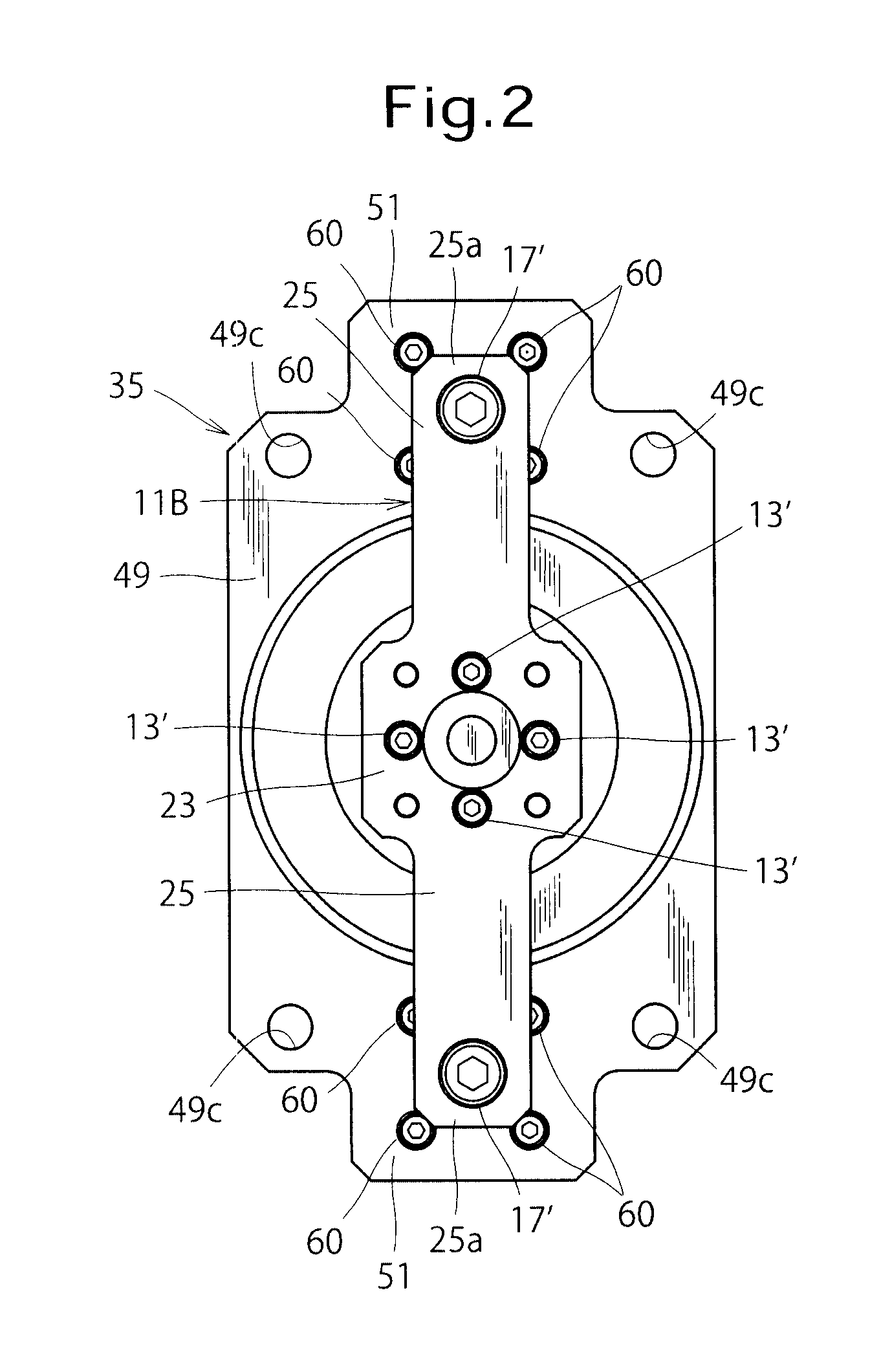
[0025]An embodiment of the present invention will be described in detail hereinbelow with reference to accompanying drawings. FIGS. 1, 2, and 3 are respectively front, left side, and right side views of a linear synchronous motor according to the embodiment of the present invention. FIG. 1 shows the linear synchronous motor that has partially been sectioned for clarity in the angular range of 90° about the axial line of a direct drive shaft 5. As shown in FIG. 1, the linear synchronous motor comprises a mover 1 and a stator 3. The mover 1 includes a direct drive shaft 5, a permanent magnet array 7 or an array of permanent magnets, a pair of guide shafts 9, a pair of connecting members 11A and 11B, and a permanent magnet 73 to be detected. The direct drive shaft 5 has an elongated cylindrical shape and is configured to reciprocate in the axial direction thereof. The permanent magnet array 7 is constituted from eight annular-shaped permanent magnets 15 fitted with the outer periphery ...


PUM


Abstract

A first pair of connected portions of one end magnetic pole portion, a first pair of connected portions of an end bracket, a first pair of connected portions of the other end magnetic pole portion, and a first pair of connected portions of each of five magnetic pole portions are connected by a pair of magnetic cylindrical members. A second pair of one connected portions of one end magnetic pole portion, a second pair of the other end magnetic pole portion, and a second pair of connected portions of each of five magnetic pole portions are connected by a pair of magnetic conductive parts. One pair of guide shafts are slidably fitted into the one pair of magnetic cylindrical members through linear bearings. A yoke is constituted from the one pair of magnetic cylindrical members and one pair of magnetic conductive parts. The five magnetic pole portions are each formed by laminating a plurality of magnetic steel plates in the axial direction.

Description

BACKGROUND OF THE INVENTION[0001]1. Field of the Invention[0002]The present invention relates to a linear synchronous motor in which a mover linearly moves relative to a stator.[0003]2. Description of the Related Art[0004]Japanese Patent Application Publication No. 2001-286122 (JP2001-286122A) discloses a linear synchronous motor comprising a stator and a mover that linearly moves relative to the stator. The mover includes a direct drive shaft reciprocating in an axial direction and an array of permanent magnets or a permanent magnet array including a plurality of permanent magnets fixed to the direct drive shaft. The stator includes a plurality of annular windings and a stator core unit having formed a slot for receiving each of the plurality of annular windings. The annular windings are each formed of an annularly wound winding conductor and are disposed so as to enclose the mover. The stator core unit is constituted from a plurality of stator core divided bodies assembled with ea...

Claims


Application Information

Patent Timeline
IPC IPC(8): H02K41/03
CPCH02K41/03
Inventor TANG, YUQISUGITA, SATOSHI
Owner SANYO DENKI CO LTD
Why Eureka
Try Eureka