Pointing system for laser designator

a laser designator and laser technology, applied in the direction of vehicle position/course/altitude control, process and machine control, instruments, etc., can solve the problems of unfavorable approach and unduly endanger

Inactive Publication Date: 2010-02-11
HONEYWELL INT INC
View PDF12 Cites 34 Cited by
  • Summary
  • Abstract
  • Description
  • Claims
  • Application Information

AI Technical Summary

Problems solved by technology

However, not only does such an approach unduly endanger ground personnel, who, in order to maintain the designated laser spot, are likely to be in the vicinity of the munition delivery point, such approach may be impracticable due to line-of-sight obstructions between the ground personnel and target.

Method used


Image

  • Pointing system for laser designator
  • Pointing system for laser designator
  • Pointing system for laser designator

Examples


Embodiment Construction

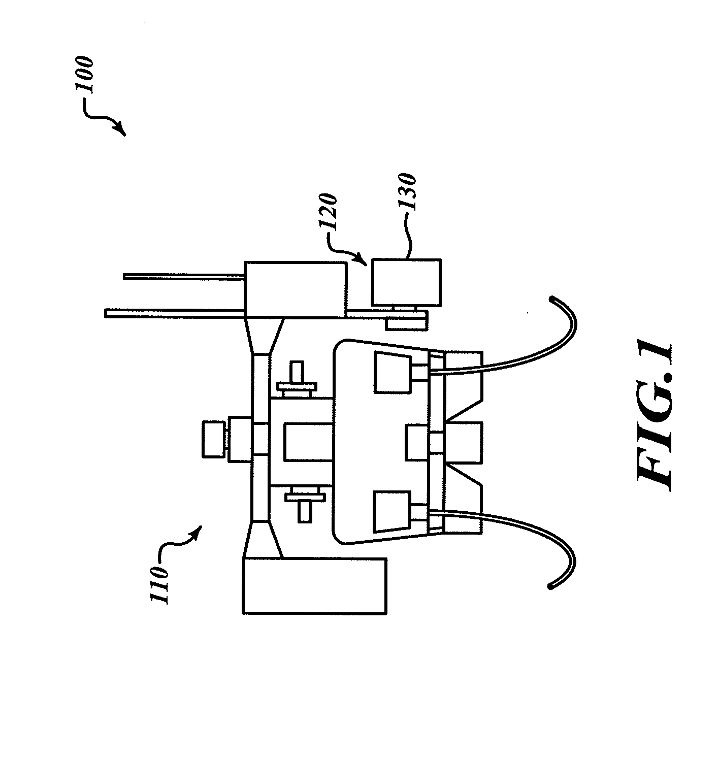
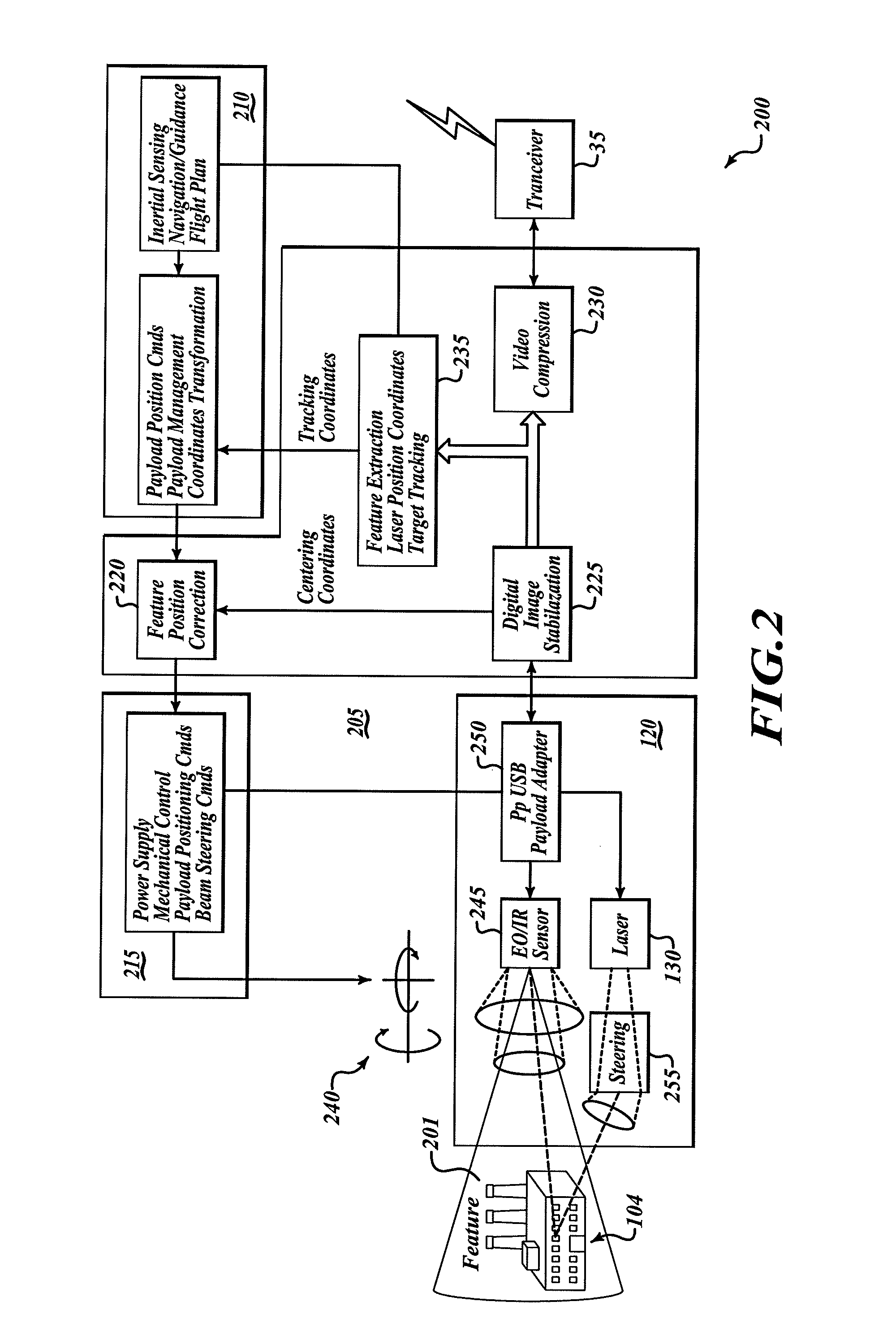
[0008]An embodiment of the invention includes an unmanned aerial vehicle (UAV) utilizing an onboard gimbaled sensor to measure designator spot error relative to a selected object of interest to which, for example, a munition is to be delivered or that is to be marked for recognition by other observers. A closed-loop system mechanically centers the designator beam in a coarse fashion, with fine beam-steering fast mirrors completing the closed-loop designation of a selected image feature.

[0009]In an embodiment, a laser designator and camera are bore sighted and mounted together on a gimbaled platform. Onboard digital-image processing hosts feature-extraction algorithms to determine positional error between a laser spot and a selected object of interest, such as a target feature. A gimbaled positioning control receives error input from the feature-extraction algorithm and closes the loop to place the spot over the selected target feature. Operationally, a user of an operator control un...


PUM


Abstract

A system for illuminating an object of interest includes a platform and a gimbaled sensor associated with an illuminator. The gimbaled sensor provides sensor data corresponding to a sensed condition associated with an area. The gimbaled sensor is configured to be articulated with respect to the platform. A first transceiver transceives communications to and from a ground control system. The ground system includes an operator control unit allowing a user to select and transmit to the first transceiver at least one image feature corresponding to the object of interest. An optical transmitter is configured to emit a signal operable to illuminate a portion of the sensed area proximal to the object of interest. A correction subsystem is configured to determine an illuminated-portion-to-object-of-interest error and, in response to the error determination, cause the signal to illuminate the object of interest.

Description

BACKGROUND OF THE INVENTION[0001]It is well known to use laser designators for target aim-point or marking designation. Some laser designation units are small enough to mount on the barrel of a pistol or rifle and are adequate for manual adjustment. There are, however, designators mounted on mobile platforms, such as a UAV, that are used for aim point designation on targets such as ground targets, tanks, or even other aircraft. For such designators, it is necessary to provide a means for maintaining the aim point at or near a fixed place on the target as the target moves in the field. It is especially critical to maintain the laser designated aim point on the target for at least the length of time it takes to launch munitions. In conventional tracking systems, the laser designated aim point is often maintained by a human operator.[0002]However, not only does such an approach unduly endanger ground personnel, who, in order to maintain the designated laser spot, are likely to be in th...

Claims


Application Information

Patent Timeline
Patent Type & Authority Applications(United States)
IPC IPC(8): G06K9/00
CPCF41G3/02G05D1/0094F41G3/145
Inventor GOOSSEN, EMRAY R.
Owner HONEYWELL INT INC
Why Eureka
Try Eureka