Fluid level sensor for a container of a negative pressure wound treatment system

Inactive Publication Date: 2010-02-11
INVACARE CONTINUING CARE
View PDF23 Cites 138 Cited by
  • Summary
  • Abstract
  • Description
  • Claims
  • Application Information

AI Technical Summary

Benefits of technology

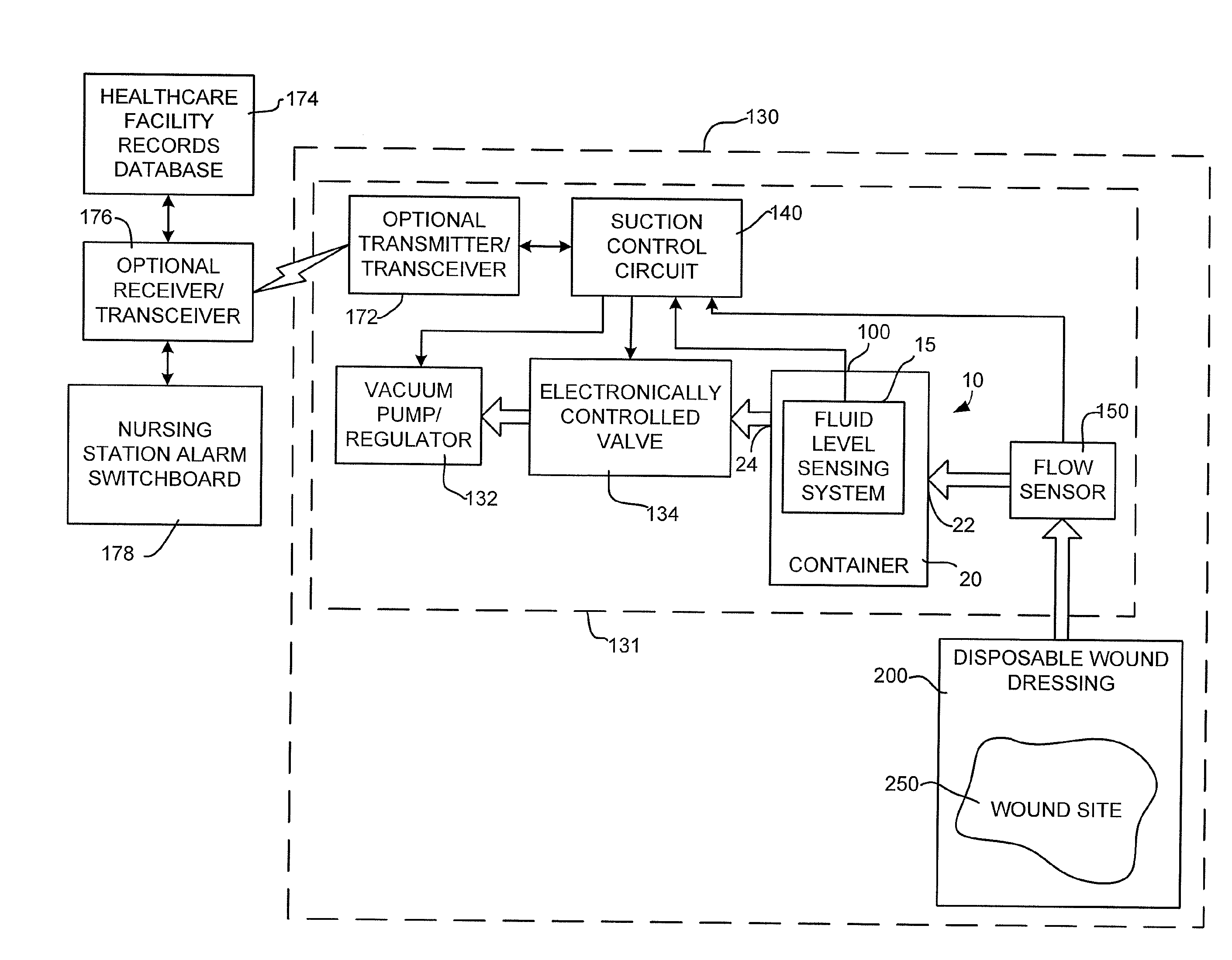
[0005]According to another aspect of the invention, a system is provided for the treatment of wounds by applying a negative pressure to a wound site. The system comprising: an electronically controlled suction regulator; a valve connected to the suction regulator for supplying a suction at an output; a medical waste collection container for collecting medical waste fluids and coupled to the output of the valve; first and second electrically conductive sensing elements disposed inside the container so as to be exposed to fluid collected in the container, where the first and second sensing elements are located inside the container at a position correspondin

Problems solved by technology

A problem with these types of mechanisms is that they may shut off the system and thus stop the negative pressure wound treatment until such tim

Method used


Image

  • Fluid level sensor for a container of a negative pressure wound treatment system
  • Fluid level sensor for a container of a negative pressure wound treatment system
  • Fluid level sensor for a container of a negative pressure wound treatment system

Examples


Embodiment Construction

[0022]Reference will now be made in detail to the presently preferred embodiments of the invention, examples of which are illustrated in the accompanying drawings. Wherever possible, the same reference numerals will be used throughout the drawings to refer to the same or like parts.

[0023]For purposes of description herein, the terms “upper,”“lower,”“right,”“left,”“rear,”“front,”“vertical,”“horizontal,”“top,”“bottom,” and derivatives thereof shall relate to the invention as shown in the drawings. However, it is to be understood that the invention may assume various alternative orientations, except where expressly specified to the contrary. It is also to be understood that the specific devices illustrated in the attached drawings and described in the following specification are simply exemplary embodiments of the inventive concepts defined in the appended claims. Hence, specific dimensions, proportions, and other physical characteristics relating to the embodiment disclosed herein are...


PUM


Abstract

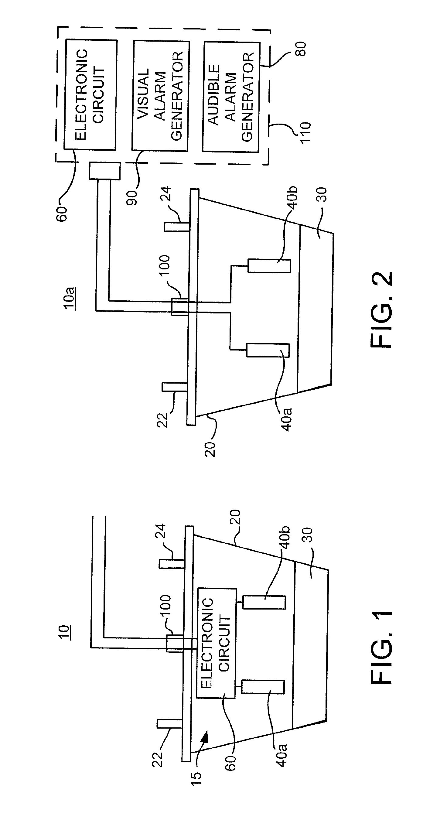
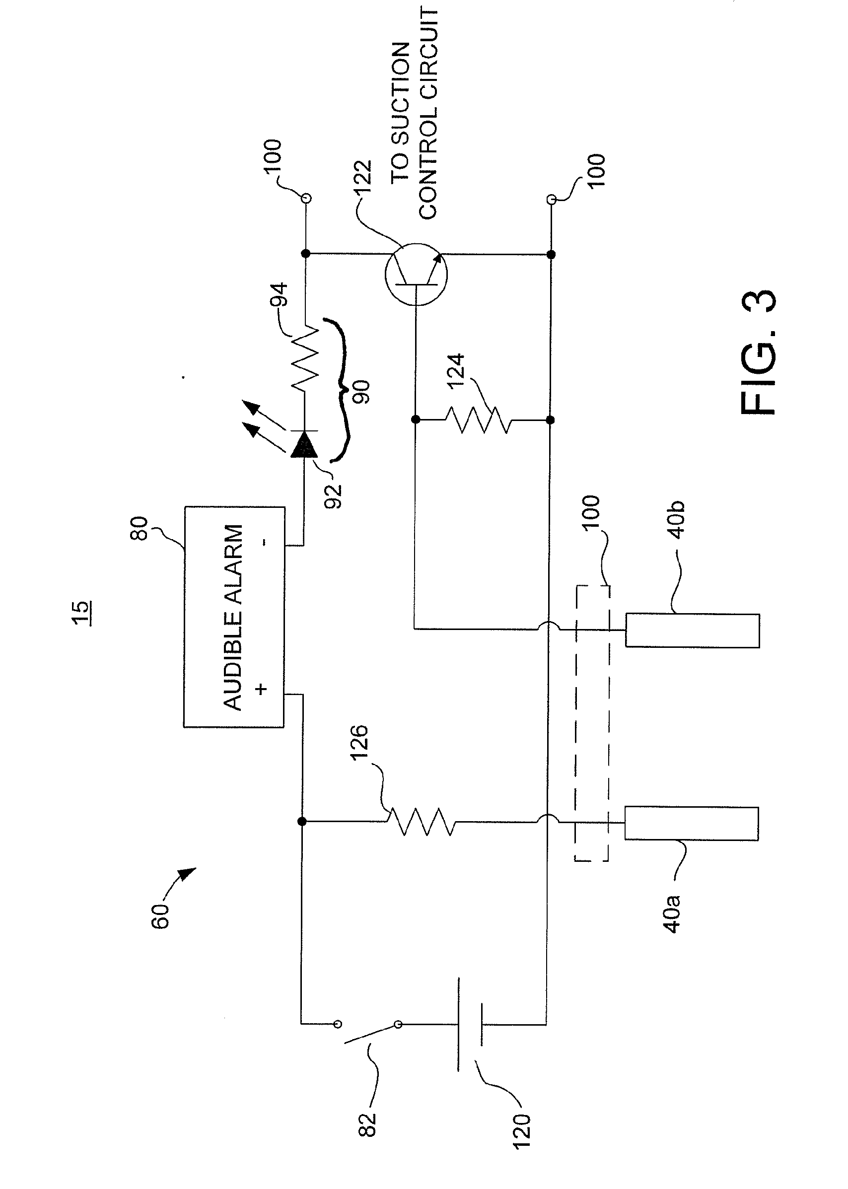
An apparatus is provided for collecting medical waste fluids. The apparatus includes: a medical waste collection container for collecting medical waste fluids; first and second electrically conductive sensing elements disposed inside the container so as to be exposed to fluid collected in the container, where the first and second sensing elements are located inside the container at a position corresponding to a full fluid level at which point the container is full of fluid; and an electronic circuit coupled to the sensing elements for generating a full alarm signal when the electronic circuit determines that current can flow between the first and second sensing elements as a result of fluid in the container reaching the full fluid level and thereby completing a current path between the first and second sensing elements.

Description

CROSS-REFERENCE TO RELATED APPLICATION[0001]This application is a continuation-in-part of U.S. patent application Ser. No. 12 / 187,114, filed on Aug. 6, 2008, the entire disclosure of which is incorporated herein by reference.BACKGROUND OF THE INVENTION[0002]The present invention is generally directed to a fluid level sensor system for a container and, for some embodiments, to a fluid level sensor system for a container used in a negative pressure wound treatment system.[0003]Wound treatment systems that treat a wound using a vacuum are known. Examples of such systems are disclosed in U.S. Pat. Nos. 4,382,441, 4,392,858, 4,655,754, 4,826,494, 4,969,880, 5,100,396, 5,261,893, 5,527,293, 5,636,643, 5,645,081, 6,071,267, 6,117,111, 6,135,116, 6,142,982, 6,174,306, 6,345,623, 6,398,767, 6,520,982, 6,553,998, 6,814,079, 7,198,046, and 7,216,651, the entire disclosures of which are incorporated herein by reference. These systems utilize either a manual pump or a portable vacuum pump to dra...

Claims


Application Information

Patent Timeline
IPC IPC(8): A61M1/00
CPCA61F2013/00174A61M1/0001A61M1/0088A61M1/0029A61M2205/18A61M2205/3382A61M1/0031A61M27/00A61M1/734A61M1/74A61M1/96A61M1/915A61M1/982A61M1/60
Inventor SCHENK, III, ALBERT A.EDDY, PATRICK E.PLATT, DAVID K.CARMICHAEL, JOSEPH A.CALLAGHAN, TERRY S.
Owner INVACARE CONTINUING CARE
Why Eureka
Try Eureka