Impingement and effusion cooled combustor component

Inactive Publication Date: 2010-02-18
GENERAL ELECTRIC CO
View PDF30 Cites 33 Cited by
  • Summary
  • Abstract
  • Description
  • Claims
  • Application Information

AI Technical Summary

Problems solved by technology

In combustor configurations utilizing impingement cooling for the combustor liner and / or transition piece (or other combustor component), it is often the case that the pitch between adjacent impingement jets tends to be too large to effectively cool the component.
Specifically, the large pitch spacing gives rise to areas which are left uncooled (sometimes referred to as “hot spots), and also to excessive thermal gradients.

Method used


Image

  • Impingement and effusion cooled combustor component
  • Impingement and effusion cooled combustor component
  • Impingement and effusion cooled combustor component

Examples


Embodiment Construction

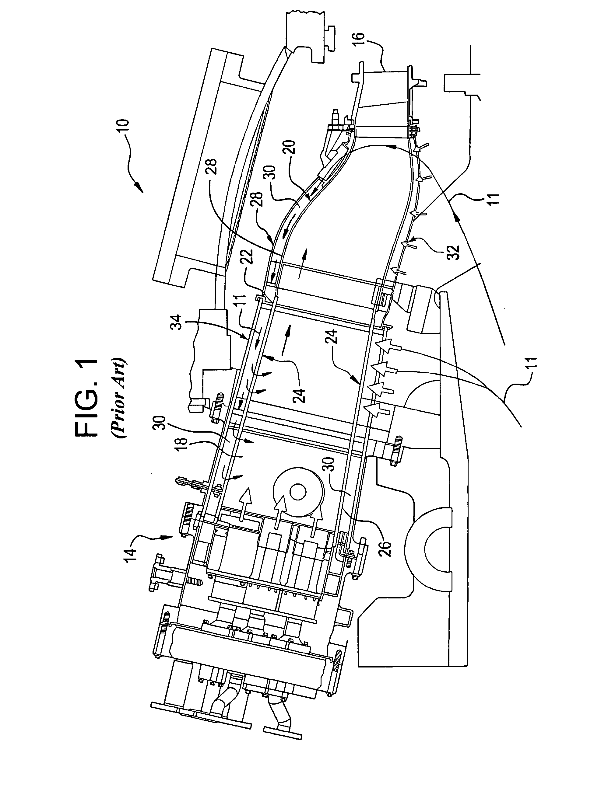
[0011]Referring to FIG. 1, a conventional can-annular reverse-flow combustor 10 is illustrated. The combustor 10 generates the gases needed to drive the rotary motion of a turbine by combusting air and fuel within a confined space and discharging the resulting combustion gases through a stationary row of vanes. In operation, discharge air (indicated by flow arrows 11) from a compressor (compressed to a pressure on the order of about 250-400 lb / sq-in) reverses direction as it passes over the outside of the combustors (one shown at 14), and again as it enters the combustor en route to the turbine (first stage nozzle indicated at 16). Compressed air and fuel are burned in the combustion chamber 18, producing gases at temperatures of about 1500° C. or about 2730° F. These combustion gases flow at high velocity into the turbine first stage nozzle 16 via transition piece 20. The transition piece 20 connects to a substantially cylindrical combustor liner 24 at connector 22, but in some app...


PUM


Abstract

A cooling arrangement for cooling a first turbine combustor component surrounded by a second component includes a first plurality of impingement cooling holes in the second component, the impingement cooling holes directing cooling air onto designated areas of the first turbine combustor component; and a second plurality of effusion cooling holes in the first turbine combustor component located to cool by effusion other areas of the first turbine combustor component.

Description

[0001]This invention relates to turbomachinery and specifically, to the cooling of combustor and transition pieces in gas turbine combustors.BACKGROUND OF THE INVENTION[0002]Conventional gas turbine combustion systems employ multiple combustor assemblies to achieve reliable and efficient turbine operation. Each combustor assembly includes a cylindrical liner, a fuel injection system, and a transition piece that guides the flow of the hot gases from the combustor to the inlet of the turbine. Generally, a portion of the compressor discharge air is used to cool the combustor liner and is then introduced into the combustor reaction zone to be mixed with the fuel and burned.[0003]In systems incorporating impingement cooled transition pieces, a hollow flow sleeve surrounds the transition piece, and the flow sleeve wall is perforated so that compressor discharge air will flow through the cooling apertures in the sleeve wall and impinge upon (and thus cool) the transition piece. This coolin...

Claims


Application Information

Patent Timeline
IPC IPC(8): F02C7/12
CPCF05B2260/201F05B2260/203F23R2900/03044F23R2900/03041F23R3/06
Inventor CHILA, RONALD J.
Owner GENERAL ELECTRIC CO
Why Eureka
Try Eureka