Turbine airfoil with trailing edge cooling channels

a technology of turbine airfoil and cooling channel, which is applied in the direction of engine fuction, machine/engine, stators, etc., can solve the problems of low blade material strength, creep, erosion, etc., and achieve the effect of increasing flow velocity and decreasing length

Inactive Publication Date: 2011-12-06
FLORIDA TURBINE TECH
View PDF26 Cites 29 Cited by
  • Summary
  • Abstract
  • Description
  • Claims
  • Application Information

AI Technical Summary

Benefits of technology

A turbine airfoil such as a turbine stator vane used in an industrial gas turbine engine, the vane including a trailing edge region having a thin wall cooling channel arrangement of mini cooling channels formed by a series of rows of elongated flow blockers that form the mini cooling channels between adjacent flow blockers. The adjacent row of flow blockers are offset from the each other such that the inlet and the outlet flow of cooling air is discharged directly onto the flow blocker in order to produce impingement cooling. The mini cooling channels have a spacing to hydraulic diameter ratio of less than 4.0 and a mini channel length to hydraulic diameter ratio of 5.0 of less in order to maintain a high flow velocity within the mini channels. In one embodiment, the flow blockers have a progressively decreasing length in the flow direction of the cooling air.

Problems solved by technology

Also, the turbine rotor blades are subject to high temperatures that lower the material strength of the blades and can lead to creep problems from long exposure to strain.
Erosion is also a problem in turbine airfoils if hot spots develop on portions of the airfoil that is not adequately cooled.
This will reduce the internal flow Mach number and through flow velocity, and thus reduce the cooling flow channel internal heat transfer coefficient as well as the channel convective performance.

Method used


Image

  • Turbine airfoil with trailing edge cooling channels
  • Turbine airfoil with trailing edge cooling channels
  • Turbine airfoil with trailing edge cooling channels

Examples


Embodiment Construction

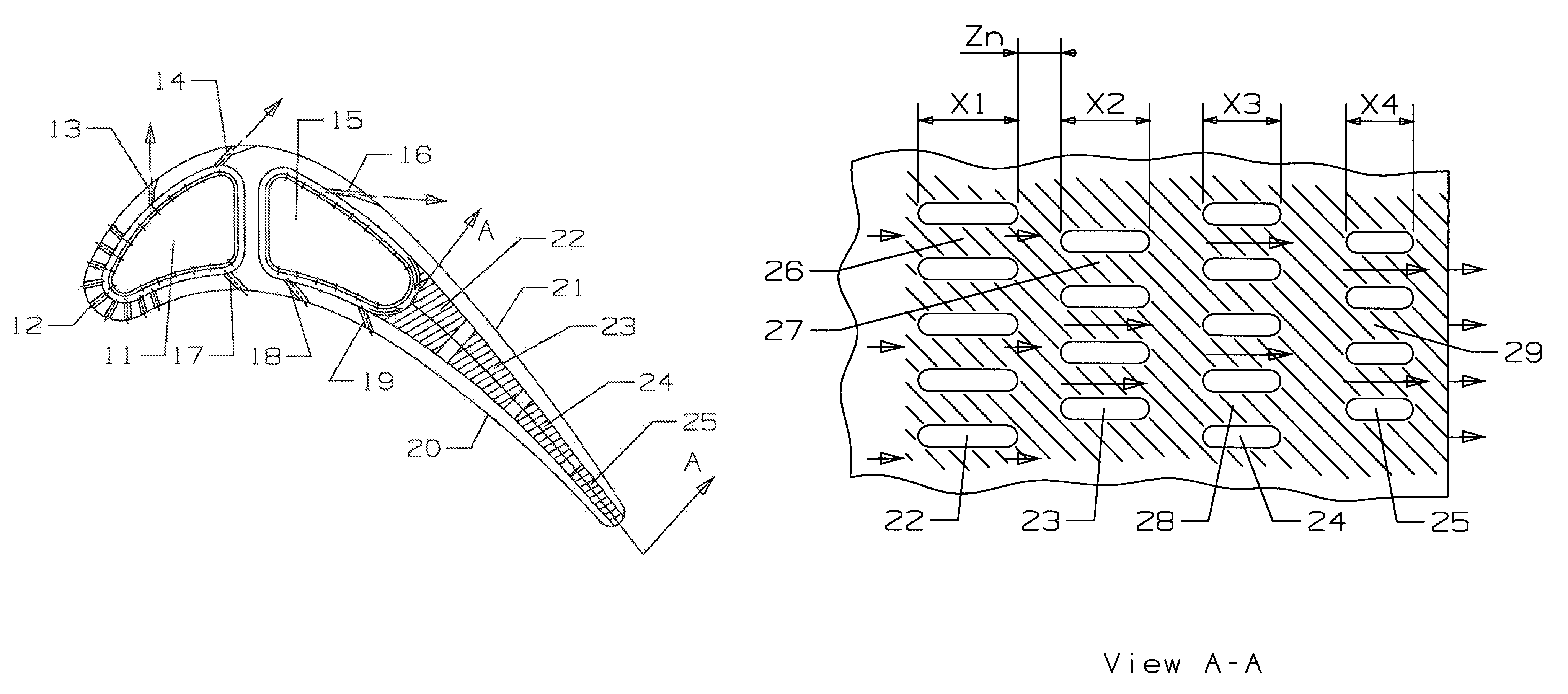
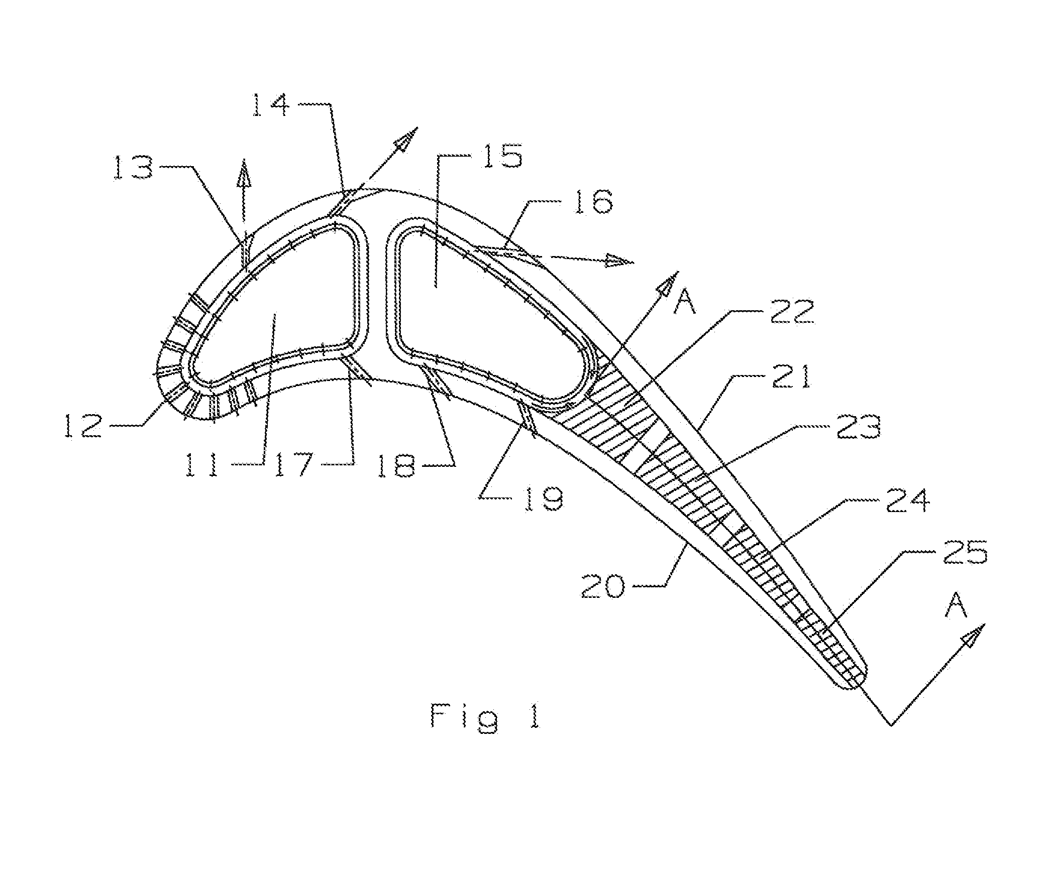
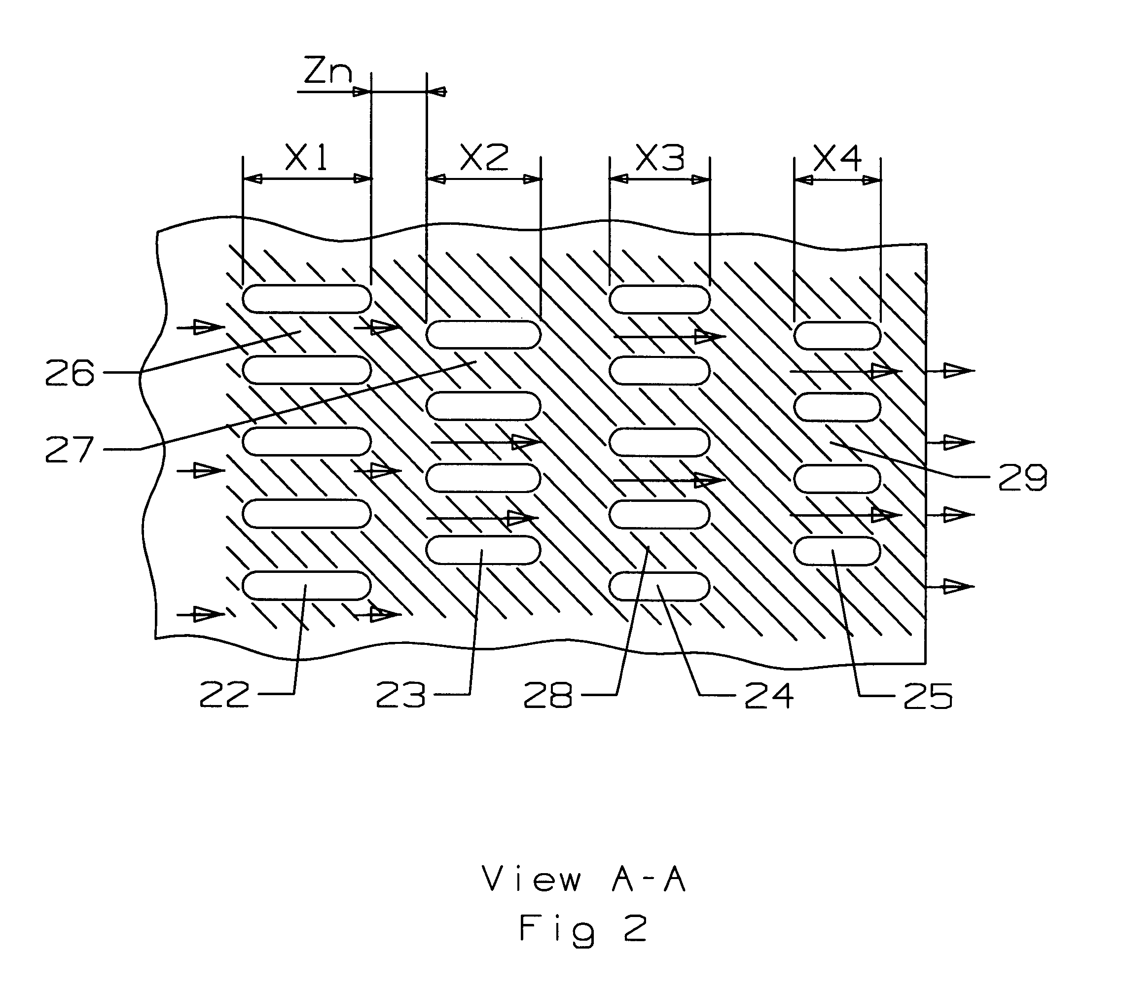
The turbine stator vane of the present invention is shown in FIG. 1 with a leading edge and a trailing edge, and a pressure side wall and a suction side wall extending between the edges and forming the airfoil portion of the blade. The invention is described for use as a turbine vane, but could also be adapted for use with a turbine rotor blade. The stator vane includes the inner and outer platform portions with an airfoil portion formed between the platforms. The vane includes one or more cooling air supply cavities that connect an external source of cooling air to the internal cooling circuit of the vane to provide for the cooling. The vane in FIG. 1 includes a leading edge cooling air supply cavity 11, an impingement plate with impingement holes formed in the plate to direct cooling air onto the inner surfaces of the vane, a showerhead arrangement of film cooling holes 12 to provide film cooling for the leading edge of the vane, a suction side gill hole or film cooling hole 13 an...


PUM


Abstract

A turbine airfoil such as a turbine stator vane used in an industrial gas turbine engine, the vane including a trailing edge region having a thin wall cooling channel arrangement of mini cooling channels formed by a series of rows of elongated flow blockers that form the mini cooling channels between adjacent flow blockers. The adjacent row of flow blockers are offset from the each other such that the inlet and the outlet flow of cooling air is discharged directly onto the flow blocker in order to produce impingement cooling. The mini cooling channels have a spacing to hydraulic diameter ratio of less than 4.0 and a mini channel length to hydraulic diameter ratio of 5.0 of less in order to maintain a high flow velocity within the mini channels. In one embodiment, the flow blockers have a progressively decreasing length in the flow direction of the cooling air.

Description

BACKGROUND OF THE INVENTION1. Field of the InventionThe present invention relates generally to fluid reaction surfaces, and more specifically to a turbine airfoil with trailing edge cooling channels.2. Description of the Related Art including information disclosed under 37 CFR 1.97 and 1.98A gas turbine engine, especially an industrial gas turbine engine, includes a turbine section with multiple stages of turbine blades and stator guide vanes to convert the energy from a hot gas flow into mechanical energy to drive the rotor shaft. The efficiency of the engine can be increased by passing a higher gas flow temperature into the turbine. However, the highest temperature that the turbine can be exposed to is related to the material characteristics of the vanes and blades in the first stage. The higher the inlet temperature to the turbine, the higher will be the engine efficiency.In order to allow for higher gas flow temperatures into the turbine, the turbine airfoils include complex int...

Claims


Application Information

Patent Timeline
Patent Type & Authority Patents(United States)
IPC IPC(8): F01D5/18
CPCF01D5/186F01D5/187F01D9/02F05D2260/201F05D2260/202F05D2260/22141
Inventor LIANG, GEORGE
Owner FLORIDA TURBINE TECH
Why Eureka
Try Eureka