Cooling concept for turbine blades or vanes

a cooling concept and turbine blade technology, applied in the direction of engine fuction, machine/engine, stators, etc., can solve the problems of high temperature of impingement cooling medium, high temperature of cooling air supplied to the aerofoil section, and possible blade or vane failure, etc., to achieve the effect of convenient and cheaper implementation

Active Publication Date: 2017-08-17
SIEMENS ENERGY GLOBAL GMBH & CO KG
View PDF14 Cites 26 Cited by
  • Summary
  • Abstract
  • Description
  • Claims
  • Application Information

AI Technical Summary

Benefits of technology

[0008]It is a first objective of the present invention to provide an advantageous aerofoil-shaped turbine assembly such as a turbine rotor blade and a stator vane with which the above described shortcomings can be can be mitigated, and especially to provide a turbine assembly that is easier and cheaper to implement in comparison with state of the art systems. A second objective of the invention is to provide a gas turbine engine comprising at least one advantageous turbine assembly.

Problems solved by technology

The effect of temperature on the turbine blades and / or stator vanes can be detrimental to the efficient operation of the turbine and can, in extreme circumstances, lead to distortion and possible failure of the blade or vane.
Problems arise when a cooling concept is used in which a temperature of a cooling medium for the impingement cooling zone is too high for efficient cooling of the latter.
The technical problem relates to the combined platform and aerofoil cooling system.
One of the main disadvantages with such a system is the elevated cooling air temperatures supplied to the aerofoil section, resulting from the heat pickup of the platform cooling.
The increase in cooling air temperature can be of the order of 50° C. When engines are significantly up-rated, the resultant coolant temperature rise through the platform cooling can be a significant factor limiting ability to achieve the required cooling levels within the aerofoil.
In such situations a significant redesign of the cooling or change of cooling feed system may be required, involving a significant amount of development and production time and cost.
A change of cooling feed system to an state of the art independent aerofoil / platform system can have the disadvantage of increased aerodynamic / performance losses, since more cooling air is discharged in the gas path in a less efficient manner, i.e. near the platform regions at undesired trajectories.

Method used


Image

  • Cooling concept for turbine blades or vanes
  • Cooling concept for turbine blades or vanes
  • Cooling concept for turbine blades or vanes

Examples


Embodiment Construction

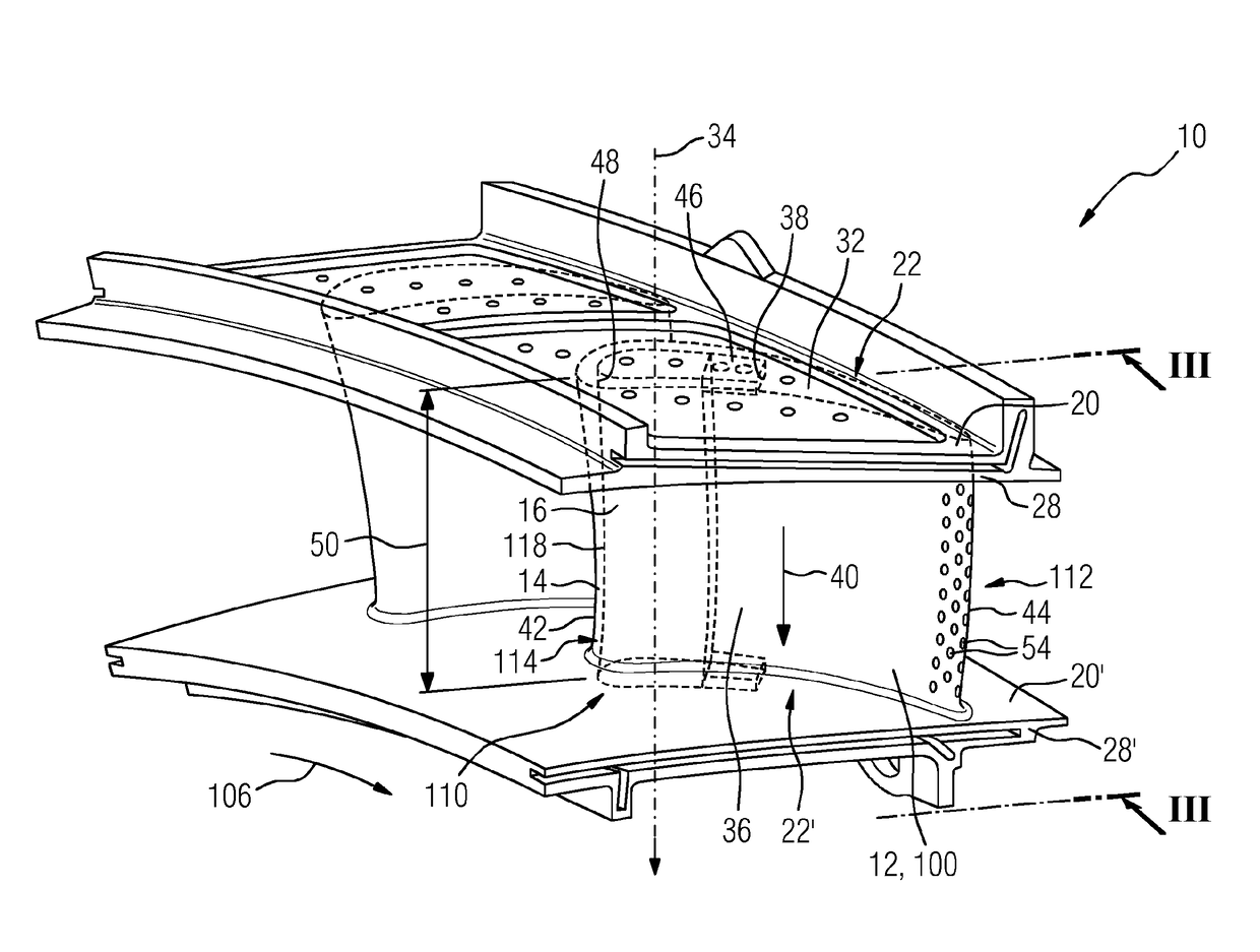
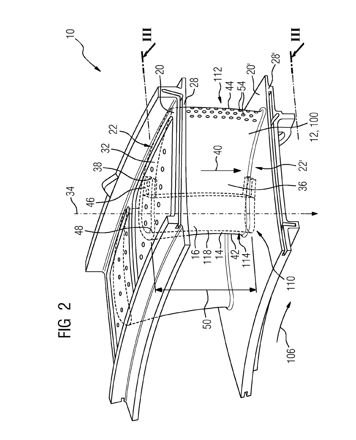
[0059]In the present description, reference will only be made to a vane, for the sake of simplicity, but it is to be understood that the invention is applicable to both blades and vanes of a gas turbine engine. The terms upstream and downstream refer to the flow direction of the airflow and / or working gas flow through the engine 64 unless otherwise stated. If used, the terms axial, radial and circumferential are made with reference to a rotational axis 74 of the engine 64.

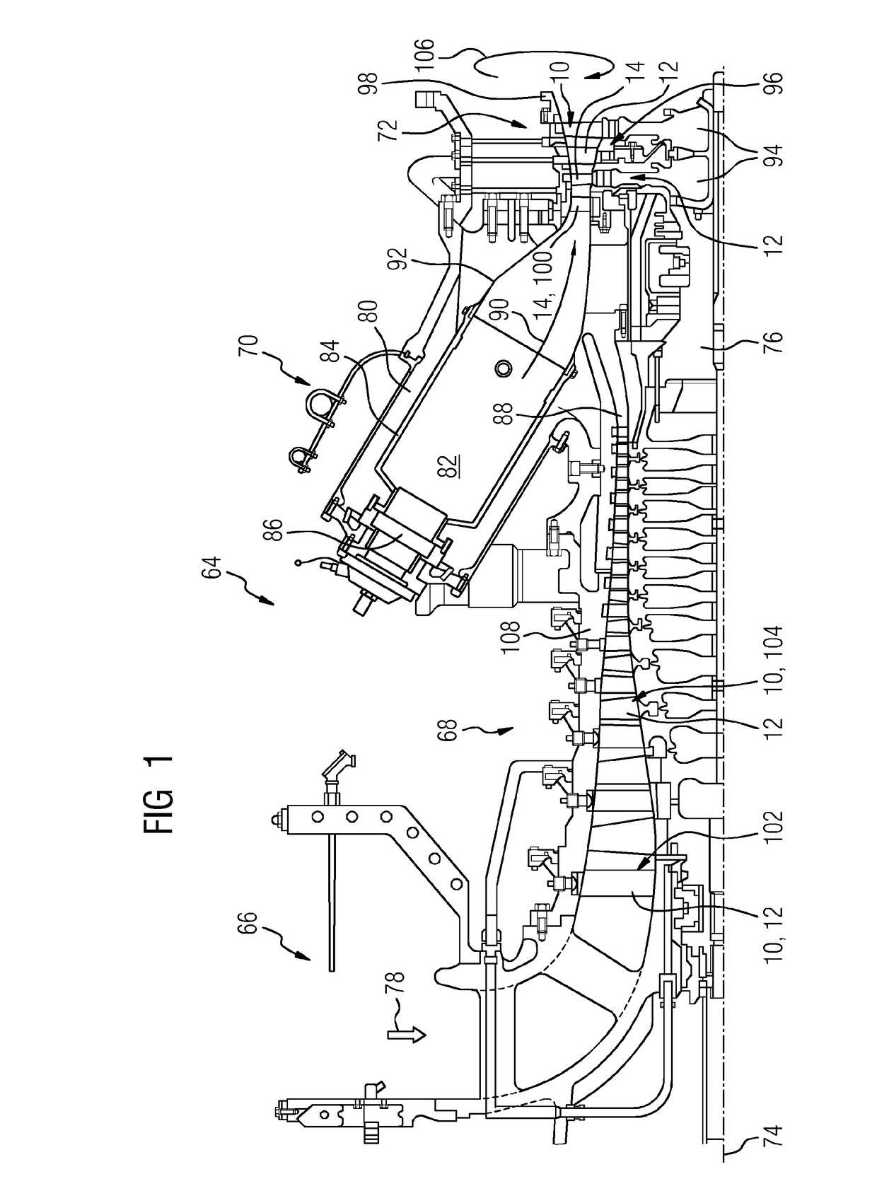
[0060]FIG. 1 shows an example of a gas turbine engine 64 in a sectional view. The gas turbine engine 64 comprises, in flow series, an inlet 66, a compressor section 68, a combustion section 70 and a turbine section 72, which are generally arranged in flow series and generally in the direction of a longitudinal or rotational axis 74. The gas turbine engine 64 further comprises a shaft 76 which is rotatable about the rotational axis 74 and which extends longitudinally through the gas turbine engine 64. The shaft 76 d...


PUM


Abstract

A turbine assembly with a hollow aerofoil having a main cavity with an impingement tube, insertable inside the main cavity for impingement cooling of an inner surface of the main cavity, and a platform at a radial end of the hollow aerofoil, and a cooling chamber for cooling the platform arranged relative to the hollow aerofoil on an opposed site of the platform. The cooling chamber is limited at a first radial end by a wall segment of the platform and at an opposed radial second end from a cover plate. The impingement tube extends in span wise direction through the cooling chamber from the platform to the cover plate and restricts a sub-cavity of the main cavity. The wall segment includes an entry aperture for a cooling medium to enter from the cooling chamber of the platform into the sub-cavity of the hollow aerofoil.

Description

CROSS REFERENCE TO RELATED APPLICATIONS[0001]This application is the US National Stage of International Application No. PCT / EP2015 / 068015 filed Aug. 5, 2015, and claims the benefit thereof. The International Application claims the benefit of European Application No. EP14182731 filed Aug. 28, 2014. All of the applications are incorporated by reference herein in their entirety.FIELD OF THE INVENTION[0002]The present invention relates to an aerofoil-shaped turbine assembly such as turbine rotor blades and stator vanes, and to impingement tubes used in such components for cooling purposes.BACKGROUND TO THE INVENTION[0003]Modern turbines often operate at extremely high temperatures. The effect of temperature on the turbine blades and / or stator vanes can be detrimental to the efficient operation of the turbine and can, in extreme circumstances, lead to distortion and possible failure of the blade or vane. In order to overcome this risk, high temperature turbines may include hollow blades ...

Claims


Application Information

Patent Timeline
Patent Type & Authority Applications(United States)
IPC IPC(8): F01D5/18F01D25/12F01D9/04
CPCF01D5/187F01D9/041F01D25/12F05D2260/201F05D2240/30F05D2240/81F05D2240/12F01D5/188F01D5/189F05D2260/205F01D5/18
Inventor MUGGLESTONE, JONATHAN
Owner SIEMENS ENERGY GLOBAL GMBH & CO KG
Why Eureka
Try Eureka