Dust Control Hood Assembly for a Cutting Machine

a technology of cutting machine and hood, which is applied in the field of cutting machine, can solve the problems of frequent adjustment of the counterbalance mechanism, and achieve the effect of facilitating the initial pivotal movement of the hood and an access to the workpi

Inactive Publication Date: 2010-02-18
META INT
View PDF18 Cites 13 Cited by
  • Summary
  • Abstract
  • Description
  • Claims
  • Application Information

AI Technical Summary

Benefits of technology

The technical effect of this patent is that it allows for easy movement of a tool's hood over a surface by providing two sets of wheels. Additionally, there is a guide at the end of the handle which helps with accessing the area where the tool will be used.

Problems solved by technology

The technical problem addressed in this patent is the frequent adjustment required for the counterbalance mechanism of a retractable dust control hood and guard for a rotary table saw due to mechanical fatigue caused by repeated extension and compression of the biasing device.

Method used


Image

  • Dust Control Hood Assembly for a Cutting Machine
  • Dust Control Hood Assembly for a Cutting Machine
  • Dust Control Hood Assembly for a Cutting Machine

Examples


Embodiment Construction

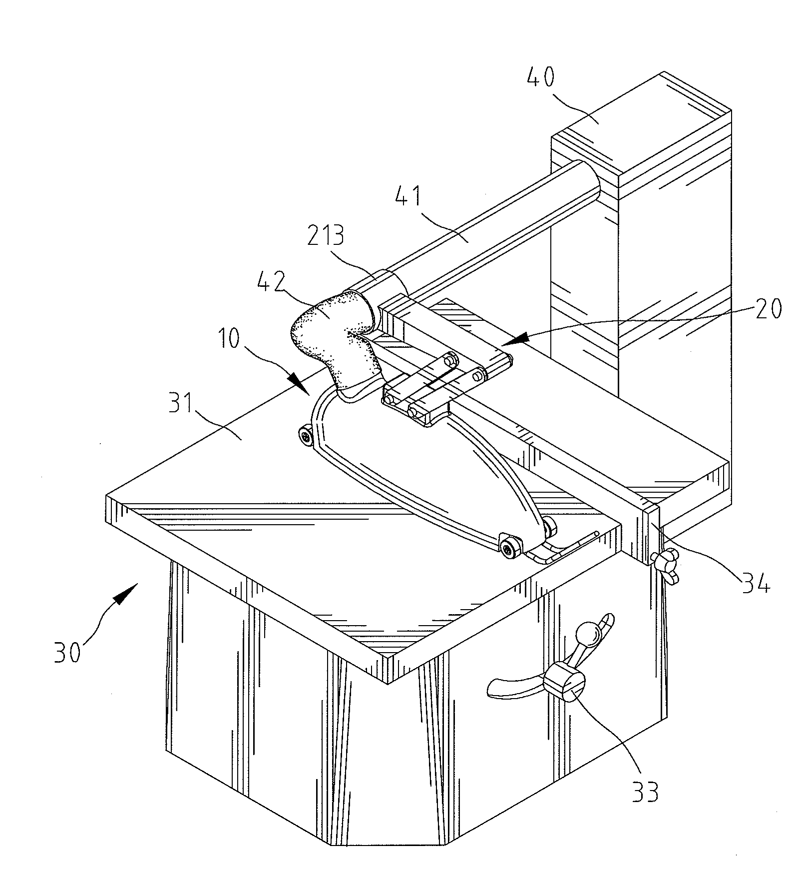
[0021]Referring to the drawings, a dust control hood assembly in accordance with the present invention is adapted to be installed to a cutting machine 30. Particularly, the cutting machine 30 includes a support surface 31 for supporting a workpiece 50 during a cutting operation, a cutting blade 32 projecting above the support surface 31, a control device 33 for making the cutting blade 32 go upward or downward, and a fence assembly 34.

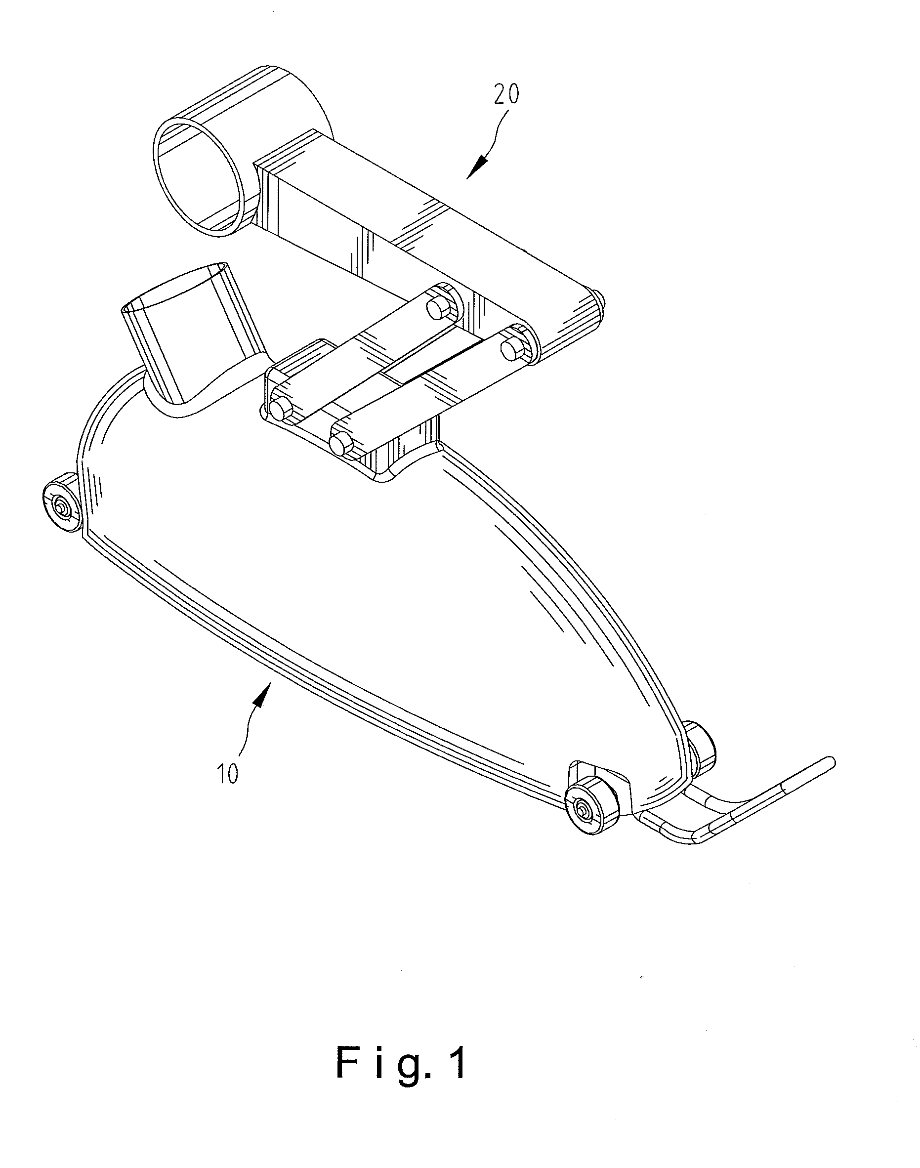
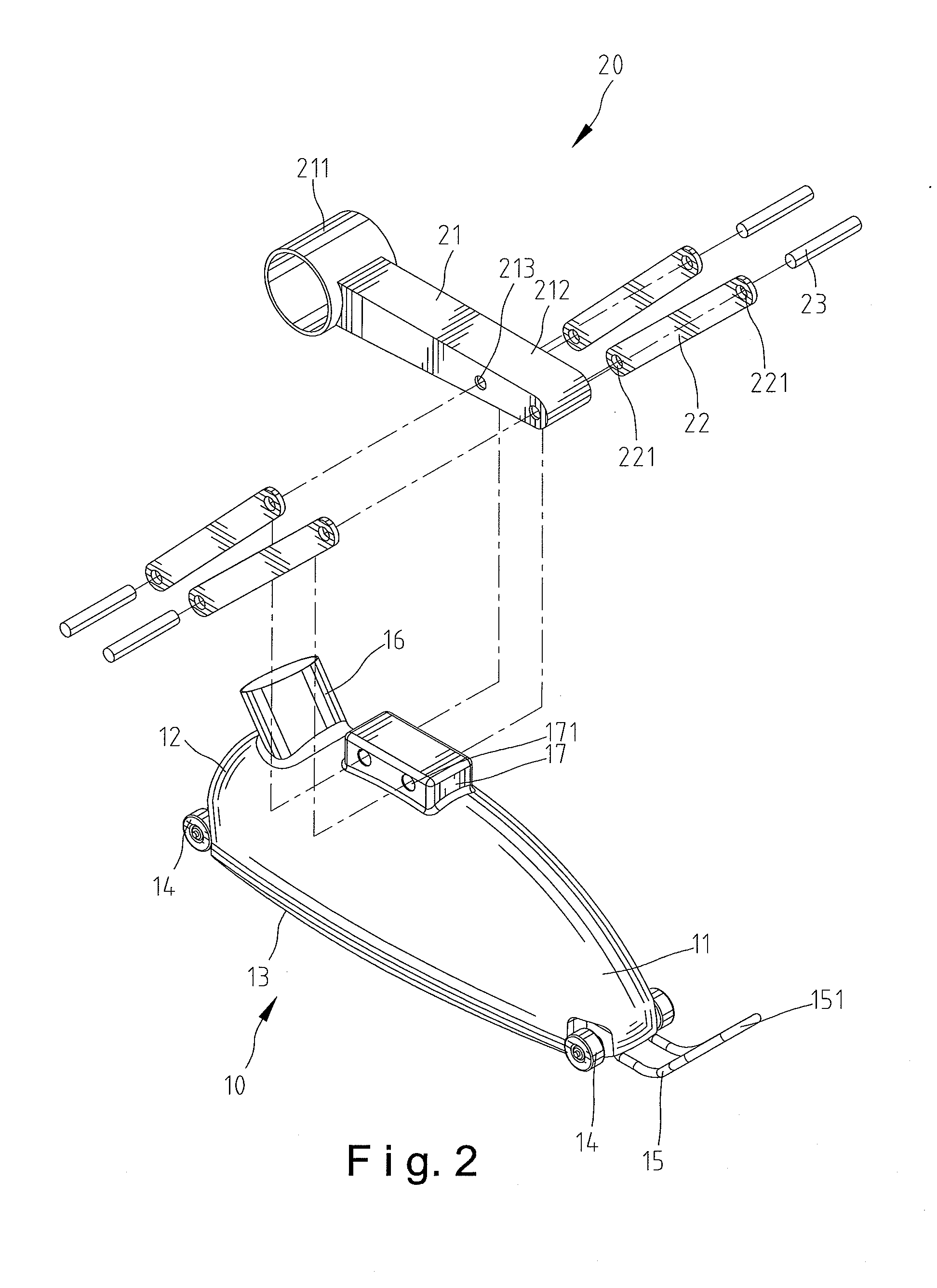
[0022]The dust control hood assembly includes a hood 10 having a cavity and an open bottom 13, adapted to encapsulate the cutting blade 32 and the workpiece 50 so that when the workpiece 50 is being cut, the hood 10 is adapted to contain the dust within the hood 10. The hood may be made of pellucid material to allow the operator to aware of the cutting process. In addition, the duct control hood assembly may utilize a dust collector 40 to evacuate the dust collected in the hood 10. In this preferred embodiment, the hood 10 includes a tube 16 extended t...


PUM

PropertyMeasurementUnit
Momentumaaaaaaaaaa
Angleaaaaaaaaaa

Abstract

A dust control hood assembly for use with a cutting machine including a hood and a lifting device. The hood includes a front end having a first set of wheels, a rear end having a second set of wheels and a handle attached to the front end thereof. The lifting device includes a fixed arm having a connecting end for fixing with a dust collector and a suspended end, and a set of pivotal arms each having a first end installed to the suspended end of the fixed arm and a second end installed to the hood. A workpiece is adapted to impose a momentum to the hood so that the hood is adapted to be lifted upward by the workpiece, and the hood is adapted to be pivoted with respect to the fixed arm.

Description


Claims


Application Information

Patent Timeline
Owner META INT
Why Eureka
Try Eureka