
PTC resistor

a resistor and characteristic technology, applied in resistors, ohmic resistance heating details, ohmic resistance heating, etc., can solve the problems of uneven heating, uneven heating, and compromise of passenger seating comfort, and achieve excellent flexibility, durability and reliability, and low manufacturing cost

Inactive Publication Date: 2010-02-18
PANASONIC INTELLECTUAL PROPERTY MANAGEMENT CO LTD
View PDF4 Cites 38 Cited by
  • Summary
  • Abstract
  • Description
  • Claims
  • Application Information

AI Technical Summary

Benefits of technology

[0023]The present invention solves these problems of the prior art, and has as its object to provide a sheet heating element with excellent flexibility, durability, and reliability, as well as low manufacturing cost. When the sheet heating element of the present invention is used in a car seat heater or in a steering wheel heater, the passenger feels comfortable when seated thereon, and the driver feels comfortable when touching the steering wheel.

Problems solved by technology

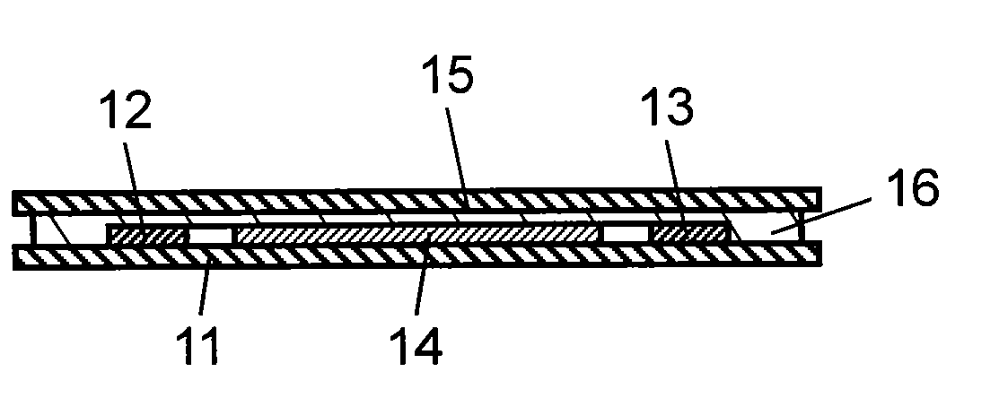
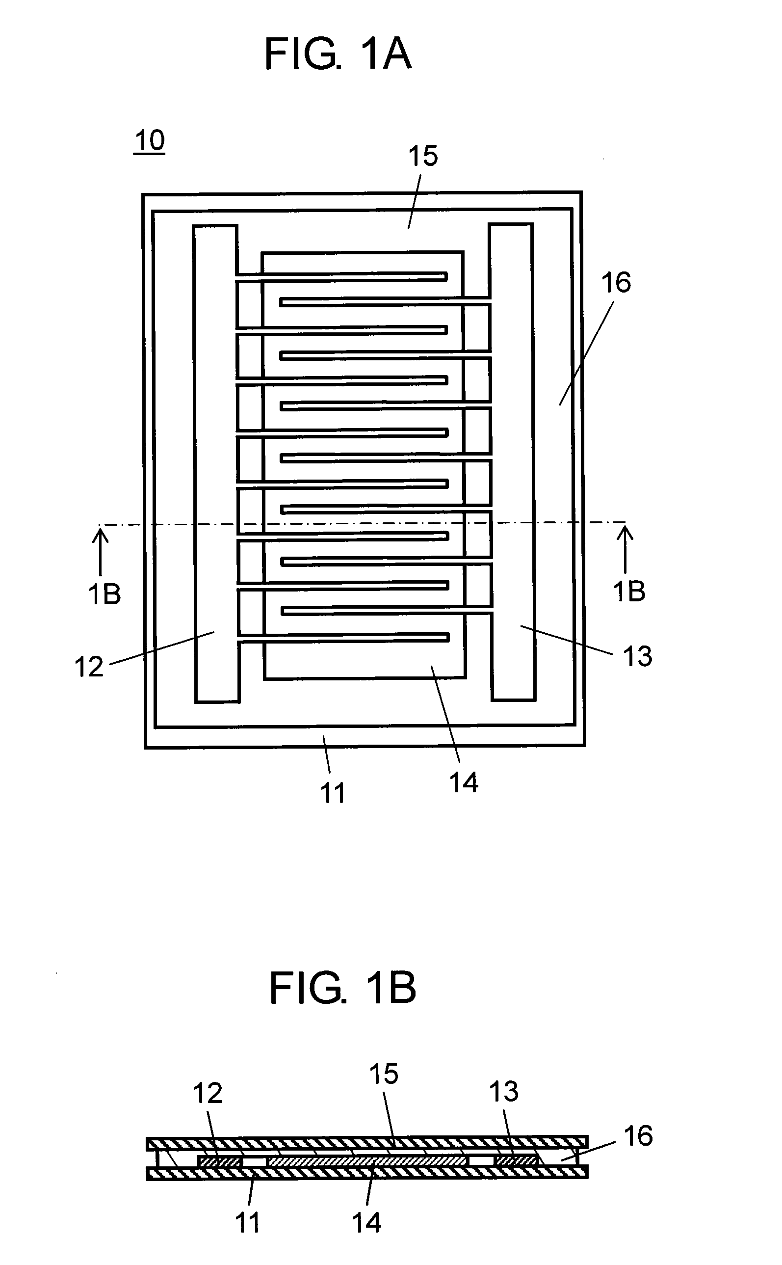
When such a sheet heating element 10 lacking in flexibility is used as a car seat heater, the passenger's seating comfort is compromised.
When such a sheet heating element 10 lacking in flexibility is used in a steering wheel heater, the comfortable gripping feel is compromised.
Thus, wrinkles form unevenly on the heating element.
Accordingly, such a heating element is thought to have low durability.
Driving or riding for a long time becomes very uncomfortable.
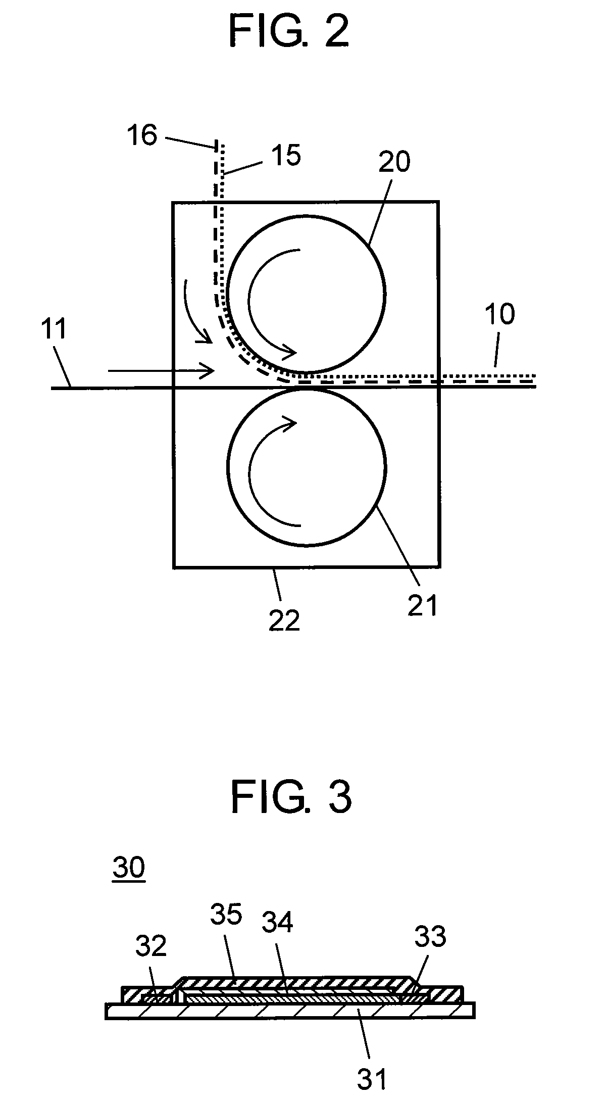
However, since the sheet heating element 30 is formed from six layers, there are the drawbacks that manufacturing productivity is low and cost is high.
At this level of PTC characteristic, the electricity consumption efficiency can by no means be considered good.
There is also the drawback that the temperature does not rise quickly.
Furthermore, the film itself has no flexibility, and there is the problem that cracks form during processing, making it difficult to form as film.Patent Reference 1: Japanese Patent Application Kokai Publication No.

Method used


Image

  • PTC resistor
  • PTC resistor
  • PTC resistor

Examples


embodiment 1

of a Sheet Heating Element

[0140]Following is a description of an embodiment of a sheet heating element using the above-described polymer resistor. FIG. 10A is a plan view of Embodiment 1 of the sheet heat element of the present invention, and FIG. 10B is a sectional view of the sheet heating element of FIG. 10A along the line 10B-10B.

[0141]A sheet heating element 100 includes an insulating substrate 101, a first line electrode 61A, a second line electrode 61B, and the polymer resistor 60. The line electrodes 61A, 61B are sometimes referred together as line electrodes 61. The line electrodes 61A, 61B are disposed right-left symmetrically on the insulating substrate 101, and are partially sewn onto the insulating substrate 101 with a thread 102. Using a T-die extruder, for example, the polymer resistor 60 can be extruded as a film onto the insulating substrate 101 onto which the line electrodes 61 have been attached, and melt-adhered together with a laminator, so as to make electrical...

embodiment 2

of a Sheet Heating Element

[0164]FIG. 12A is a plan view of the sheet heating element 120 of Embodiment 2 of the present invention, and FIG. 12B is a sectional view along the line 12B-12B in FIG. 12A. The structure differs from that of Embodiment 1 (see FIG. 10A, 10B) in that line electrodes 121 are arranged in wavy lines on the insulating substrate 101.

[0165]As shown in FIG. 12A, the line electrodes 121 are arranged in wavy lines on the insulating substrate 101, being attached by a thread 102. In accordance with this structure, when an external force is applied to the sheet heating element 120, since the line electrodes 121 are arranged in wavy lines, having leeway in terms of length, they readily change the shape in response to tension, stretching, and bending. Therefore, the wave line electrodes 121 have mechanical strength with respect to external force superior to that of the line electrodes 61.

[0166]Furthermore, in regions where the wave line electrodes 121 run, the voltage app...

embodiment 3

of a Sheet Heating Element

[0167]FIG. 13A is a plan view of the sheet heating element 130 of Embodiment 3 of the present invention, and FIG. 13B is a sectional view along the line 13B-13B in FIG. 13A. The structure differs from that of Embodiment 1 (see FIGS. 10A, 10B) in that auxiliary line electrodes 131 are arranged between the pair of line electrodes 61. In other words, auxiliary line electrodes 131 are arranged between the pair of line electrodes 61, and are sewn onto the insulating substrate 101 by sewing machine, using a thread 132 made of polyester fibers or the like, as in the case of the line electrodes 61.

[0168]In the structure shown in FIG. 10A, the polymer resistor 60 is prone to be unevenly heated between the line electrodes 61, and the resistivity for that portion rises, concentrating the electric potential there. If this state continues, temperature of that part of the polymer resistor 60 increases more than other parts, resulting in what is known as the hot-line phen...


PUM


Abstract

A PTC resistor according to the present invention comprises at least one PTC composition which comprises at least one resin and at least two conductive materials. The at least two conductive materials comprises at least two conductive materials different from each other. The at least one PTC composition may comprise a first PTC composition which comprises a first resin and at least one first conductive material and a second PTC composition which is compounded with the first PTC composition and comprises a second resin and at least one second conductive material. The at least one first conductive material is at least partially different from the at least one second conductive material. One of the first resin and the second resin may comprise a reactant resin and a reactive resin which is cross-linked with the reactant resin. The PTC resistor may comprise a flame retardant agent. The PTC resistor may comprise a liquid-resistant resin.

Description

TECHNICAL FIELD[0001]The present invention relates to a resistor having a PTC characteristic, and in particular, the present invention relates to a polymer resistor composition with an excellent PTC characteristic, and a highly reliable sheet heating element using this polymer resistor composition. The sheet heating element has a characteristic of being so highly flexible that it can be mounted on a surface of any shape of an appliance.BACKGROUND ART[0002]PTC characteristic refers to a characteristic such that when the temperature rises, resistance rises with it. A sheet heating element having such a PTC characteristic has self-temperature control of the heat which it emits. Heretofore, a resistor was used in the heat-emitting member of such a sheet heating element. This resistor was formed from a resistor ink composed of a base polymer and a conductive material dispersed in a solvent.[0003]This resistor ink is printed on a base material forming a heating element. The ink is dried, ...

Claims


Application Information

Patent Timeline
Patent Type & Authority Applications(United States)
IPC IPC(8): H05B3/10
CPCH01C7/021H01C7/027H05B3/146H05B3/34H05B2203/005H05B3/03H05B2203/013H05B2203/017H05B2203/026H05B2203/029H05B2214/04H05B2203/011H05B2203/006H05B3/20
Inventor FUKUDA, HIROSIUNO, KATSUHIKOISHII, TAKAHITONAKAJIMA, KEIZOUMEDA, AKIHIRO
Owner PANASONIC INTELLECTUAL PROPERTY MANAGEMENT CO LTD
Learn More