
Stereotactic drive system

Active Publication Date: 2010-02-18
MONTERIS MEDICAL
View PDF101 Cites 43 Cited by
  • Summary
  • Abstract
  • Description
  • Claims
  • Application Information

AI Technical Summary

Benefits of technology

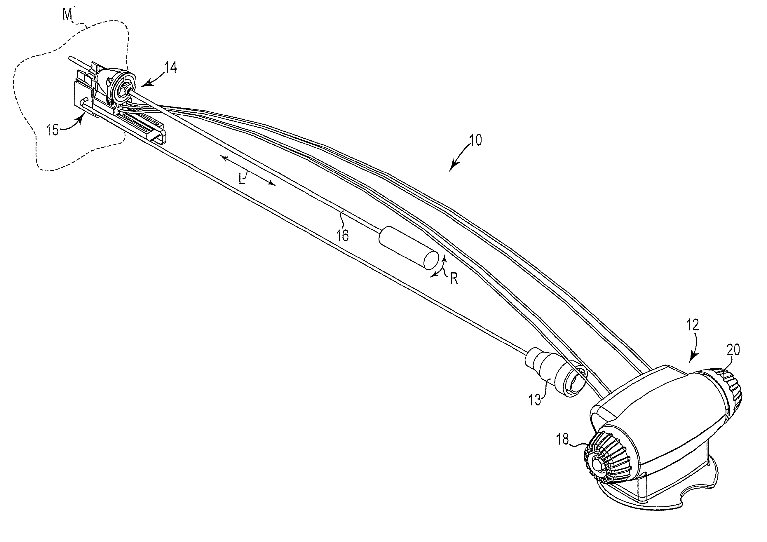
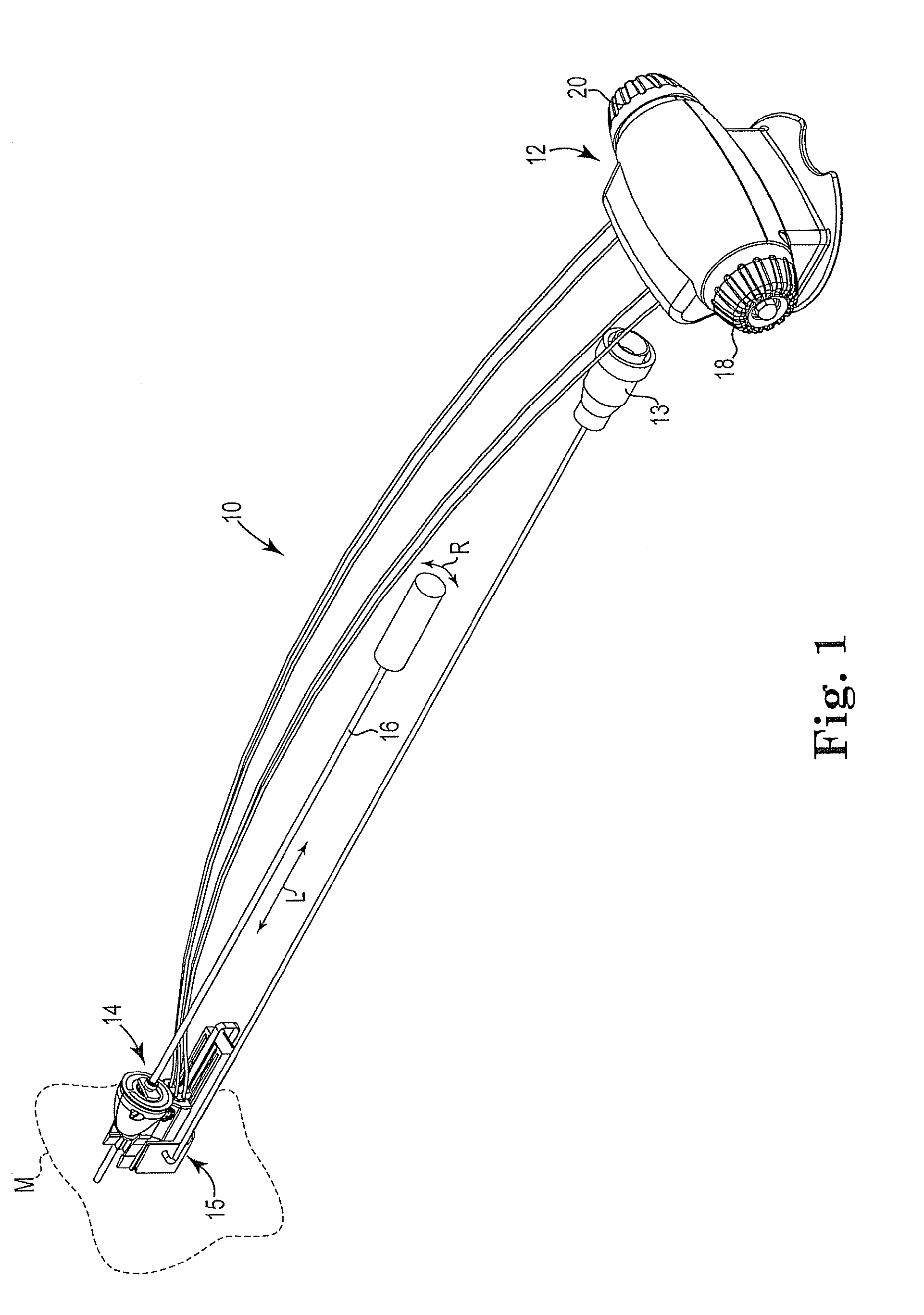
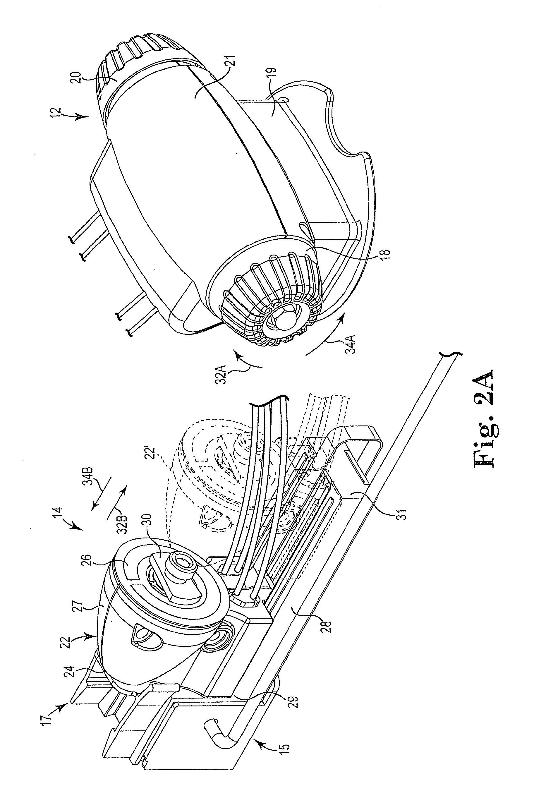
[0024]The present invention solves the foregoing problems by providing a drive system for controlling movement of an elongate member including a base unit having a first rotatable knob and a second rotatable knob, a follower assembly including a follower slidably coupled to a guide rail, a longitudinal movement wire, and a rotational movement wire. The follower includes a longitudinal movement pulley, a rotational movement pulley, and an alignment element structured to receive an elongate member such that the elongate member is attachable thereto. The longitudinal movement wire operably couples the first rotatable knob to the longitudinal movement pulley such that rotation of the first knob drives the follower in a longitudinal direction along the guide rail. The rotational movement wire operably couples the second rotatable knob to the rotational movement pulley such that rotation of the second knob rotates the alignment element and attached elongate member.

Problems solved by technology

However, the other roughly 183,000 of these tumors are “malignant” (i.e., cancerous), meaning that they are capable of causing or contributing to patient death.
However, these single masses can often be quite large, irregularly-shaped, multi-lobed and / or infiltrated into surrounding brain tissue.
However, by the time the symptoms develop the tumor may already be large and aggressive.
However, by its very nature, surgery is highly invasive and risky.
Furthermore, for some tumors surgery is often only partially effective.
In other tumors, the surgery itself may not be feasible, it may risk impairment to the patient, it may not be tolerable by the patient, and / or it may involve significant cost and recovery.
However, confirmation that the tumor has been killed or neutralized is often not possible for several months post-treatment.
Furthermore, in situations where high doses of radiation may be required to kill a tumor, such as in the case of multiple or recurring tumors, it is common for the patient to reach the “toxic threshold” prior to killing all of the tumors, where further radiation is inadvisable.
Malignant tumors, because of their high vascularization and altered DNA, are more susceptible to heat-induced damage than normal tissue.
Therefore, it is difficult for the surgeon to effect a controlled heating which heats the entire tumor to a required level while also minimizing damage to the surrounding tissue.
However, movement of the patient, together with the partial excision or coagulation of some of the tissue, can significantly change the location of the tumor to be excised.
The disclosure of the patent has not led to a commercially viable hyperthermic treatment system.
Again this patented arrangement has not led to a commercially viable hyperthermia surgical system.
This type of treatment does not incorporate a monitoring system to monitor and control the effect of the shock waves.
This arrangement has not achieved commercial or medical success.
Once again, this arrangement does not provide feedback control of the heating effect.
In particular, this arrangement uses high speed pulsed laser energy for a photo-disruption effect, but does not disclose methods of feedback control of the energy.
While highly effective in certain applications, the use of ITT to treat brain tumors has been limited by the inability to focus the energy exclusively and precisely on the tumor so as to avoid damage to surrounding normal brain tissue.
This is complicated by the fact that many brain tumors are highly irregular in shape.
Therefore, a heretofore unaddressed need exists to establish a drive system for an elongate member that is capable of precisely controlling both the longitudinal and rotational positions of the elongate member with respect to a target, such as a tumor mass.

Method used


Image

  • Stereotactic drive system
  • Stereotactic drive system
  • Stereotactic drive system

Examples


Embodiment Construction

[0041]The present invention involves a drive system for stereotactic positioning of an elongate member. The elongate member may include, for example, elongate probes, catheters, endoscopes, and the like. However, those skilled in the art will appreciate that the drive system of the present invention may be used in conjunction with any elongate member requiring precise control in a longitudinal and / or rotational direction.

[0042]In one exemplary embodiment, the drive system in accordance with the present invention may be used to control the precise movement of a laser probe insertable into the skull of a patient for the treatment of tumors. In particular, and as will be evident to one skilled in the art based upon the following disclosure and corresponding figures, the drive system may be operated to position a distal end of a probe at precise locations within the tumor through both controlled longitudinal and rotational movement of the probe.

[0043]Referring now to FIG. 1, there is sh...


PUM


Abstract

A drive system for controlling movement of an elongate member includes a base unit having a first rotatable knob and a second rotatable knob, a follower assembly including a follower slidably coupled to a guide rail, a longitudinal movement wire, and a rotational movement wire. The follower includes a longitudinal movement pulley, a rotational movement pulley, and an alignment element structured to receive an elongate member such that the elongate member is attachable thereto. The longitudinal movement wire operably couples the first rotatable knob to the longitudinal movement pulley such that rotation of the first knob drives the follower in a longitudinal direction along the guide rail. The rotational movement wire operably couples the second rotatable knob to the rotational movement pulley such that rotation of the second knob rotates the alignment element and attached elongate member.

Description

CROSS-REFERENCE TO RELATED APPLICATION(S)[0001]This application claims the benefit of U.S. Provisional Application Ser. No. 61 / 088,969, filed Aug. 14, 2008, the entirety of which is hereby incorporated by reference.BACKGROUND OF THE INVENTION[0002]The present invention relates generally to control systems. More specifically, the present invention relates to a drive system for controlling the longitudinal movement and rotational position of an elongate member.[0003]Each year roughly 200,000 patients are diagnosed with brain tumors in the United States. Roughly 17,000 of these tumors are “benign,” meaning that the tumor mass is not cancerous. However, the other roughly 183,000 of these tumors are “malignant” (i.e., cancerous), meaning that they are capable of causing or contributing to patient death. Approximately 10% of cancerous brain tumors are “primary” tumors, meaning that the tumors originate in the brain. The primary tumors typically consist of brain tissue with mutated DNA tha...

Claims


Application Information

Patent Timeline
IPC IPC(8): A61B19/00
CPCA61B17/3403A61B18/20A61B19/22A61B19/201A61B2017/3409A61B2019/2242G05G1/10A61B19/26A61B34/70A61B34/71A61B90/50A61B90/11A61B34/20
Inventor QURESHI, SALMANGRANT, MARKFERNANDES, LUIS FILIPE SILVA
Owner MONTERIS MEDICAL
Learn More