Measuring method and system for components, in particular for pistons and piston engines

a technology for piston engines and components, applied in the field of measuring techniques, can solve the problems of insufficiently complex components, considerable time expenditure on resetting, and inability to meet the requirements of aforementioned time expenditur

Active Publication Date: 2010-02-18
MAHLE INT GMBH
View PDF4 Cites 5 Cited by
  • Summary
  • Abstract
  • Description
  • Claims
  • Application Information

AI Technical Summary

Problems solved by technology

Systems hitherto available on the market can identify and compensate for these disturbing influences only very inadequately for more complex components.
These threshold values are for the most part selected fixed over the whole measuring section and / or over a lengthy timespan during the testing of a number of components and satisfy only simple dynamics, so that the aforementioned problems and the aforementioned time expenditure cannot be satisfactorily avoided.
The drawback with all these methods is the sometimes considerable time expenditure on resetting the measuring system, the checking and recalibration of the system which has to be carried out in a narrow time-slot, as well as the false measurement results and incorrect assessments resulting due to disturbing influences even with optimum adjustment—also due to non-critical variations of the properties of the components with respect to one another, N.B. the failure to recognise rejects or the rejection of good parts.

Method used


Image

  • Measuring method and system for components, in particular for pistons and piston engines
  • Measuring method and system for components, in particular for pistons and piston engines
  • Measuring method and system for components, in particular for pistons and piston engines

Examples


Embodiment Construction

[0023]An example of embodiment with a rotationally symmetric component is described in detail in connection with the drawings.

[0024]In the drawings:

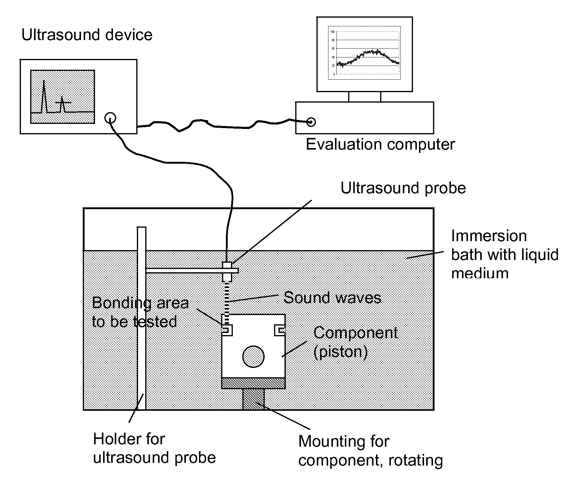
[0025]FIG. 1 shows a schematic view of a commercially available measuring system, such as can also be used for the invention;

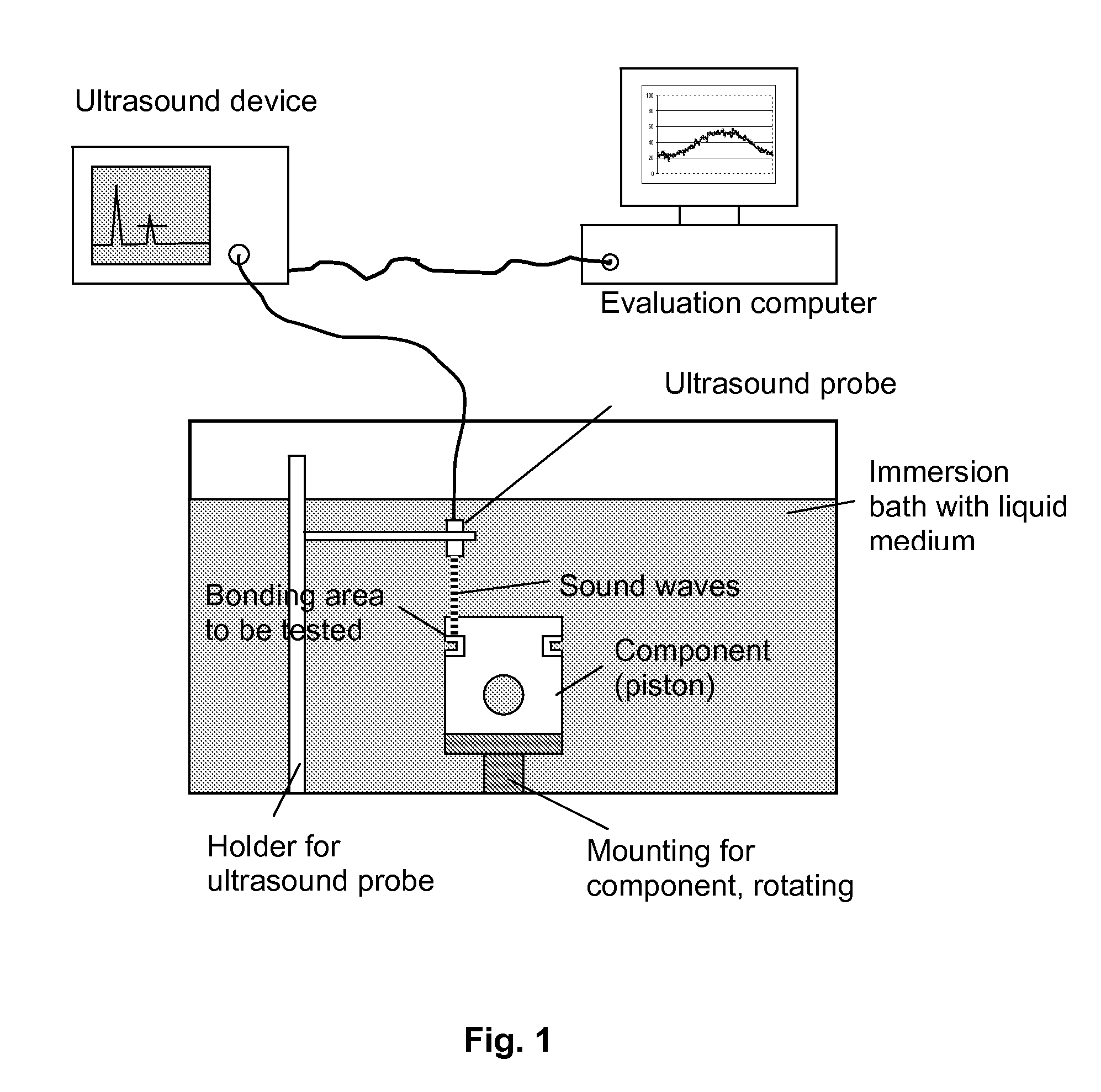
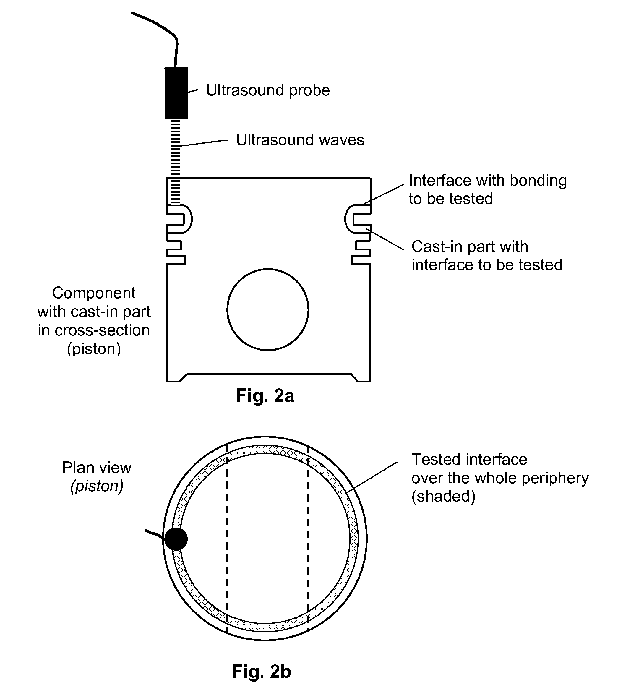
[0026]FIG. 2a shows in cross-section a piston of an internal combustion engine as a typical component for the application of the method according to the invention;

[0027]FIG. 2b shows the plan view of the piston shown in FIG. 2a;

[0028]FIG. 3a shows an “ideal measured-value curve” over the range of ascertained amplitude values;

[0029]FIG. 3b shows an actual curve over the range of ascertained amplitude values, falsified by a long-wave superimposition;

[0030]FIG. 4a shows a curve for an actually fault-free part, but which is measured according to the prior art and rejected as defective;

[0031]FIG. 4b shows a curve for an actually defective part, but which is measured according to the prior art and thus labelled as fault...


PUM

PropertyMeasurementUnit
reflectionaaaaaaaaaa
transmission methodaaaaaaaaaa
entropyaaaaaaaaaa

Abstract

The invention relates to the non-destructive measurement of components, in particular the functional assessment of the bonding of cast-in parts, eg. in pistons for internal combustion engines. With such a measurement or functional assessment, it is a question of assessing the function and completeness of the bonding between the base material and the material cast in or otherwise joined. The quality of the component or its suitability for a specific purpose can thus be assessed and/or quality monitoring of the production process, e.g. in the foundry or during production, can take place. According to the invention, this purpose is served by a multi-stage correction procedure, wherein the measured values ascertained by means of a suitably devised measuring arrangement and method, e.g. using ultrasound, are subjected to a multi-stage determination process, which minimises universally and for each individual measurement the disturbing factors which, being inherent in the system, occur in the measurement and ascertains therefrom the desired results. A correspondingly devised system minimises both error influences, which occur in the performance (especially with the setting-up/adjustment) of such a measurement, as well as measurement errors and incorrect assessments in the performance of the measurement, which occur due to geometrical tolerance deviations or differences between a number of components to be measured or due to differences in the material or structural composition, as well as other disturbing influences.

Description

TECHNICAL FIELD OF THE INVENTION[0001]The invention lies in the field of measuring techniques and relates to the measurement of rotary parts, in particular pistons for internal combustion engines and other piston engines. With such measurements, it is important to ascertain accurate, often complex measurements rapidly and with as little time expenditure as possible. For example, the suitability of a piston or another rotary part for a specific application can thus be assessed or quality monitoring can be carried out during the production of the component.[0002]In the present case, it concerns the non-destructive measurement and functional assessment of the bonding of cast-in parts or similar arrangements in components, in particular the determination of the metallic bonding of cast-in parts in pistons for internal combustion engines. With such a measurement, it is a question of assessing the function and completeness of the bonding along a defined area between the base material and ...

Claims


Application Information

Patent Timeline
Patent Type & Authority Applications(United States)
IPC IPC(8): G01N29/48G01N29/04G06F19/00
CPCG01N29/11G01N29/4472G01N2291/048G01N2291/044G01N29/48G01M15/04G01M15/00
Inventor SCHNELL, HOLGER
Owner MAHLE INT GMBH
Why Eureka
Try Eureka