Method for producing wiring harness

Active Publication Date: 2010-02-25
YAZAKI CORP
View PDF5 Cites 44 Cited by
  • Summary
  • Abstract
  • Description
  • Claims
  • Application Information

AI Technical Summary

Benefits of technology

[0024]According to the method for producing a wiring harness of the present invention described above, a grommet and a fixing member such as a clip are previously assembled with a good-handling corrugate tube. Then, a plurality of high-voltage electrical power lines are inserted into the corrugate tube, thereby a wiring harness can be relatively easily produced. Further, this wiring harness allows to be easily wired. Further, according to the structure of the wiring harness described above, not only productivity but also handling ability are improved. In thi

Problems solved by technology

Therefore, there is a problem that productivity is relatively low.
Further, because using the metallic pipes, there is a problem that handling ability is low not only during the wiring harness production but also after the

Method used


Image

  • Method for producing wiring harness
  • Method for producing wiring harness
  • Method for producing wiring harness

Examples


Embodiment Construction

[0037]A wiring harness according to the present invention will be explained with reference to figures.

[0038]A wiring harness of this embodiment is used in a hybrid vehicle or an electric vehicle. Hereafter, a case that the wiring harness is used in the hybrid vehicle is explained. (In a case of the electric vehicle, a structure, a configuration, and an effect of the wiring harness are basically the same.)

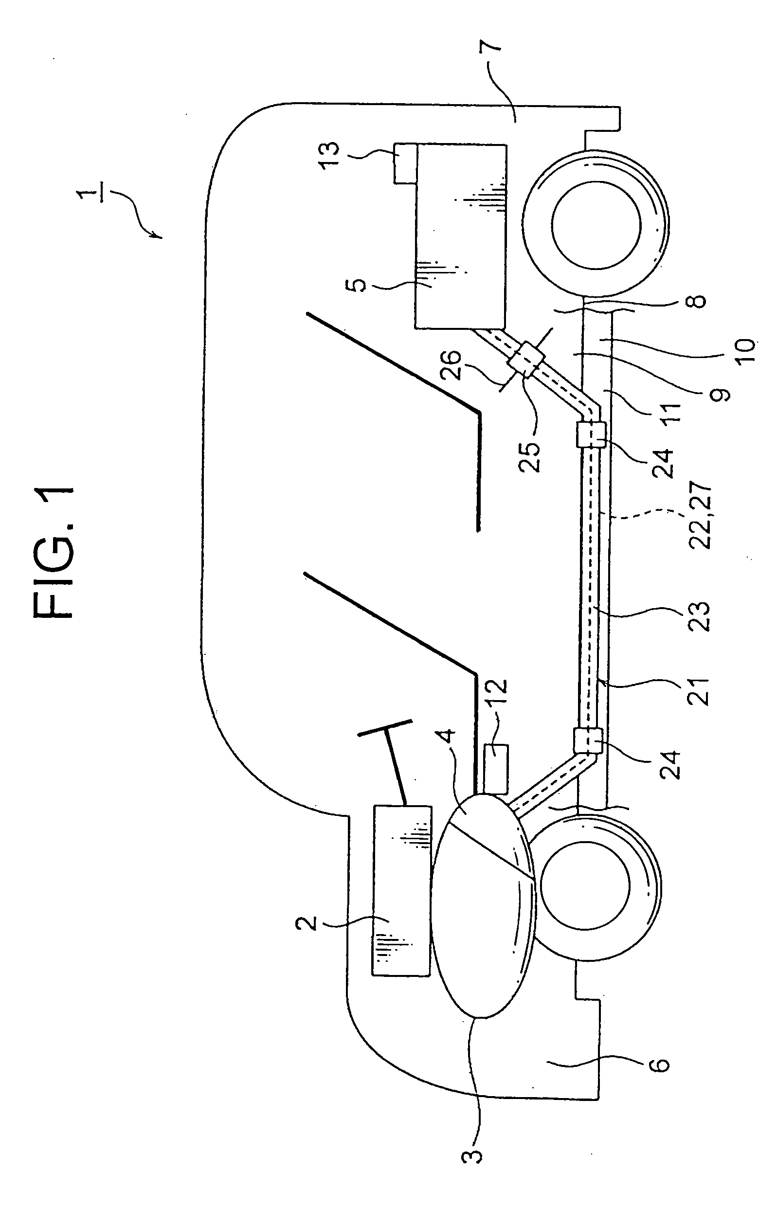
[0039]In FIG. 1, a reference numeral 1 indicates a hybrid vehicle. The hybrid vehicle 1 mixes driving forces of an engine 2 and a motor 3. A battery 5 supplies an electric power to the motor 3 via an inverter 4. In this embodiment, the engine 2, the motor 3, and the inverter 4 are mounted on a front side 6 of an inner vehicle body where front wheels are disposed. Further, the battery 5 is mounted on a rear side 7 of the inner vehicle body where rear wheels are disposed.

[0040]A reference numeral 8 indicates a vehicle body frame. In FIG. 1, an upper side of the vehicle body frame 8 in...


PUM

PropertyMeasurementUnit
Electric potential / voltageaaaaaaaaaa

Abstract

In a first production process, firstly, a flat corrugate tube 23 having a necessary length for wiring is prepared. Next, a grommet 25 and a protector 24 are assembled with the flat corrugate tube 23 at predetermined positions. In a second production process, high-voltage power lines 22 and low-voltage electric wires 27 are inserted into the flat corrugate tube 23 from the one opening 40 toward the other opening 41. In a third production process, ends of the high-voltage power lines 22 and the low-voltage electric wires 27 exposed from the one opening 40 and the other opening 41 of the flat corrugate tube 23 are treated. When the third production process is finished, the production of the wiring harness 21 is finished.

Description

CROSS REFERENCE TO RELATED APPLICATIONS [0001]This application is on the basis of Japanese Patent Application No. 2008-210249, the contents of which are hereby incorporated by reference.BACKGROUND OF THE INVENTION [0002]1. Field of the Invention[0003]The present invention relates to a method for producing a wiring harness.[0004]2. Description of the Related Art[0005]A wiring harness disclosed in Patent Document 1 listed below includes: three high-voltage electrical power lines; and three metallic protection pipes respectively receiving thee high-voltage electrical power lines. The high-voltage electrical power lines connect a motor mounted at a front side of a vehicle to an inverter mounted at a middle or rear side of the vehicle.[0006]The wiring harness is arranged via an under floor of a vehicle body disposed at an outside of a vehicle body frame. Therefore, the metallic protection pipe protects the high-voltage electrical power line from a jumping stone or spattering water. Furth...

Claims


Application Information

Patent Timeline
IPC IPC(8): H01R11/00
CPCB60R16/0207Y10T29/49117Y10T29/49174H01R43/28
Inventor OGA, TATSUYAICHIKAWA, HIDEHIROOGUE, TAKESHI
Owner YAZAKI CORP
Why Eureka
Try Eureka