Indicator apparatus

a technology of indicator apparatus and pointer, which is applied in the direction of indication apparatus, transportation and packaging, instruments, etc., can solve the problems of increasing the manufacture cost of variable display elements and the inability to manufacture dials inexpensively, so as to prevent overshoot and pulsation of pointers

Inactive Publication Date: 2010-02-25
NIPPON SEIKI CO LTD
View PDF26 Cites 6 Cited by
  • Summary
  • Abstract
  • Description
  • Claims
  • Application Information

AI Technical Summary

Benefits of technology

[0015]The present invention relates to an indicator apparatus in which a pointer is secured to a pointer drive means by at

Problems solved by technology

Such a structure, however, requires a punching step of forming a through hole for passing through the rotation shaft in the dial that complicates the manufacture of the dial, thereby causing the problem of the inability to manufacture the dial inexpensively.
Especially, when a variable displ

Method used


Image

  • Indicator apparatus
  • Indicator apparatus
  • Indicator apparatus

Examples


first embodiment

[0042]In the following, a first embodiment in which the present invention is applied to a vehicle combination meter will be described with reference to the accompanying drawings.

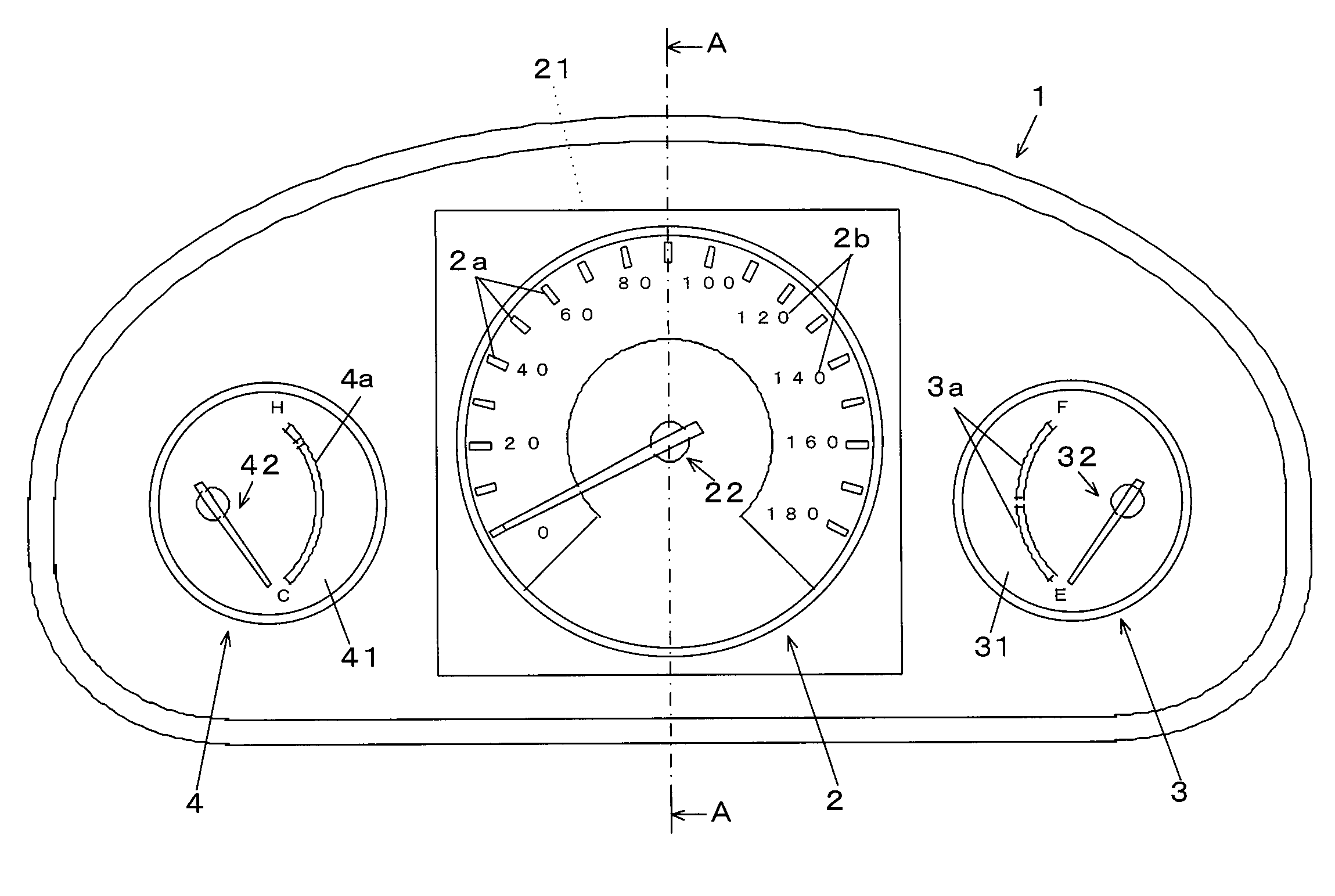
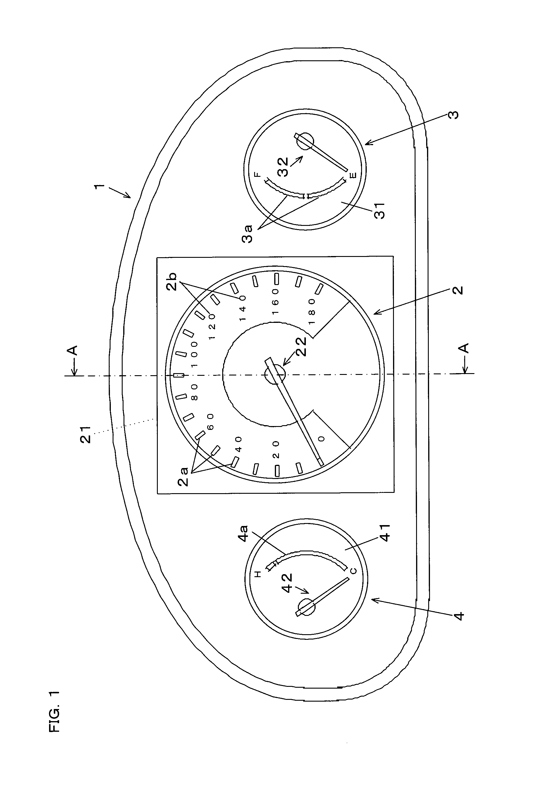
[0043]In FIG. 1, reference numeral 1 shows a housing. The housing 1 has a shade member and a case body to accommodate three indicators, that is, a speed meter 2, a fuel meter 3, and a water-temperature meter 4. The speed meter 2 is larger than the fuel meter 3 and water-temperature meter 4 and is placed between the fuel meter 3 and the water-temperature meter 4. The speed meter 2 has a display plate 21 and a pointer 22. The fuel meter 3 and the water-temperature meter 4 have dials 31, 41, and pointers 32, 42, respectively. The dials 31, 41 are provided by forming light-shield portions through printing on substrates made of light-transmitting resin (for example, polycarbonate) except for indicating portions 3a, 4a, respectively. The pointers 32, 42 are rotated by a stepping motor (not shown) to point at the i...

second embodiment

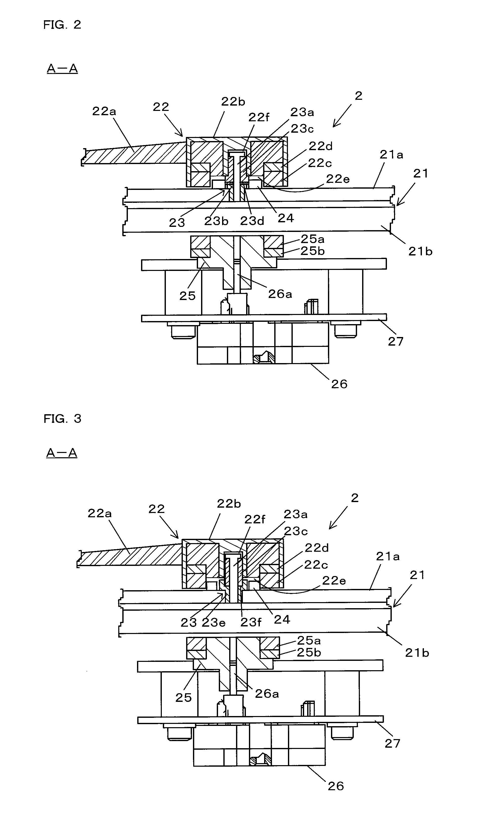
[0063]In the shaft portion 23, a main-shaft receive portion 23e has, at the top end, a hollow portion 23f which contains viscous damper oil (liquid form, not shown), and the bottom end of the rotation shaft portion 23c is located in the hollow portion 23f, as a method of adjusting the frictional force of the rotation shaft portion 23c instead of the washer 23d. The main-shaft receive portion 23e is made of the non-magnetic material as described above. With the structure, in the second embodiment, since the rotation shaft portion 23c is immersed in the damper oil, the viscosity of the damper oil can suppress an overshoot and pulsation in association with the rotation of the pointer 22 (damping effect) to provide a more appropriate structure for fixing the pointer 22.

[0064]While the first and second magnets 22c, 25a are permanent magnets in the first and second embodiments, the second magnet 25a may be an electromagnet, for example. An organic EL element may be used as the variable di...


PUM


Abstract

To provide an indicator apparatus in which a pointer is secured to a pointer drive means by attraction force of magnets and the pointer can be secured more tightly to prevent an overshoot and pulsation of the pointer. The indicator apparatus has a display plate 21, a pointer 22 provided on a front-face side of the display plate 21, a pointer drive means provided on a back-face side of the display plate 21 for rotating the pointer 22, a first magnet 22c in a ring shape provided for the pointer 22, and a second magnet 25a provided for the pointer drive means to be opposite to the first magnet 22c, in which the pointer 22 is rotated in association with rotation drive of the pointer drive means by attraction force of the first and second magnets 22c, 25a. A shaft portion 23 rotatably supporting the pointer 22 is located in the display plate 21. The shaft portion 23 includes a main shaft23a, a main-shaft receive portion 23b securing the main shaft 23a to the display plate 21, and a rotation shaft portion 23c provided rotatably about the main shaft 23a and located on and secured to the pointer 22.

Description

TECHNICAL FIELD[0001]The present invention relates to an indicator apparatus in which a pointer points at an indicating portion on a display plate.BACKGROUND ART [0002]There have been conventionally indicator apparatuses in which a pointer points at an indicating portion on a dial (display plate). In such an indicator apparatus, the pointer is directly secured to a rotation shaft of a pointer drive means such as a stepping motor, and the pointer is rotated in association with rotation drive of the pointer drive means and thus caused to point at the indicating portion.[0003]Such a structure, however, requires a punching step of forming a through hole for passing through the rotation shaft in the dial that complicates the manufacture of the dial, thereby causing the problem of the inability to manufacture the dial inexpensively. Especially, when a variable display element such as a liquid crystal display element is used for the dial as disclosed in Patent Document 1, a through hole sh...

Claims


Application Information

Patent Timeline
IPC IPC(8): G01D13/22
CPCG01D13/22B60K2350/1064B60K37/02B60K2370/154G01D2213/10
Inventor MASUDA, HIDEKIKAWAMURA, TATSUKI
Owner NIPPON SEIKI CO LTD
Why Eureka
Try Eureka