Wind Turbine

a wind turbine and wind power technology, applied in the direction of wind power generation, motors, dynamo-electric machines, etc., can solve the problems of heavy and expensive stator structures, difficulty in maintaining the width of the air gap at least substantially constant at the unsupported side of the stator, etc., and achieve the effect of widening the air gap

Active Publication Date: 2010-02-25
SIEMENS GAMESA RENEWABLE ENERGY AS
View PDF22 Cites 32 Cited by
  • Summary
  • Abstract
  • Description
  • Claims
  • Application Information

AI Technical Summary

Benefits of technology

[0026]In particular in this case it is advantageous, when the width of the air gap between the stator arrangement and the rotor arrangement is measured by means of at least one distance sensor and / or by interpretation of the generated currents and / or voltages of the direct drive generator. The at least one distance sensor is able to be attached on the rotor arrangement or on the stator arrangement to measure the width of the air gap. But it is also possible to interpret or evaluate the generated currents and / or voltages of the direct drive generator during operation and e.g. to compare the resulting values with known or calibrated reference values for which the width of the air gap was determined. Thus also in this way the actual width of the air gap is able to be determined. By a continuous or an intermittent measurement of the width of the air gap, the width of the air gap is able to be actively monitored.

Problems solved by technology

The drawback of such a design is that the one-side support of the stator makes it difficult to maintain the width of the air gap at least substantially constant at the unsupported side of the stator in particular when the entire generator structure is not only subject to gravity and mass inertia but also to unbalanced magnetic pull.
A drawback of this design is that the stator structure needs to be dimensioned to absorb and transfer all wind turbine rotor loads, i.e. the weight of the wind turbine rotor and all asymmetric aerodynamic loads to maintain the width of the air gap within the necessary tolerances.
On large wind turbines this leads to very heavy and expensive stator structures.

Method used


Image

  • Wind Turbine
  • Wind Turbine
  • Wind Turbine

Examples


Embodiment Construction

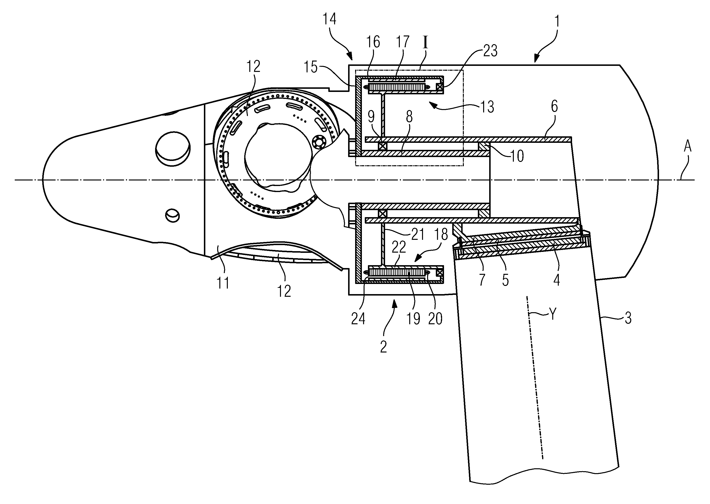
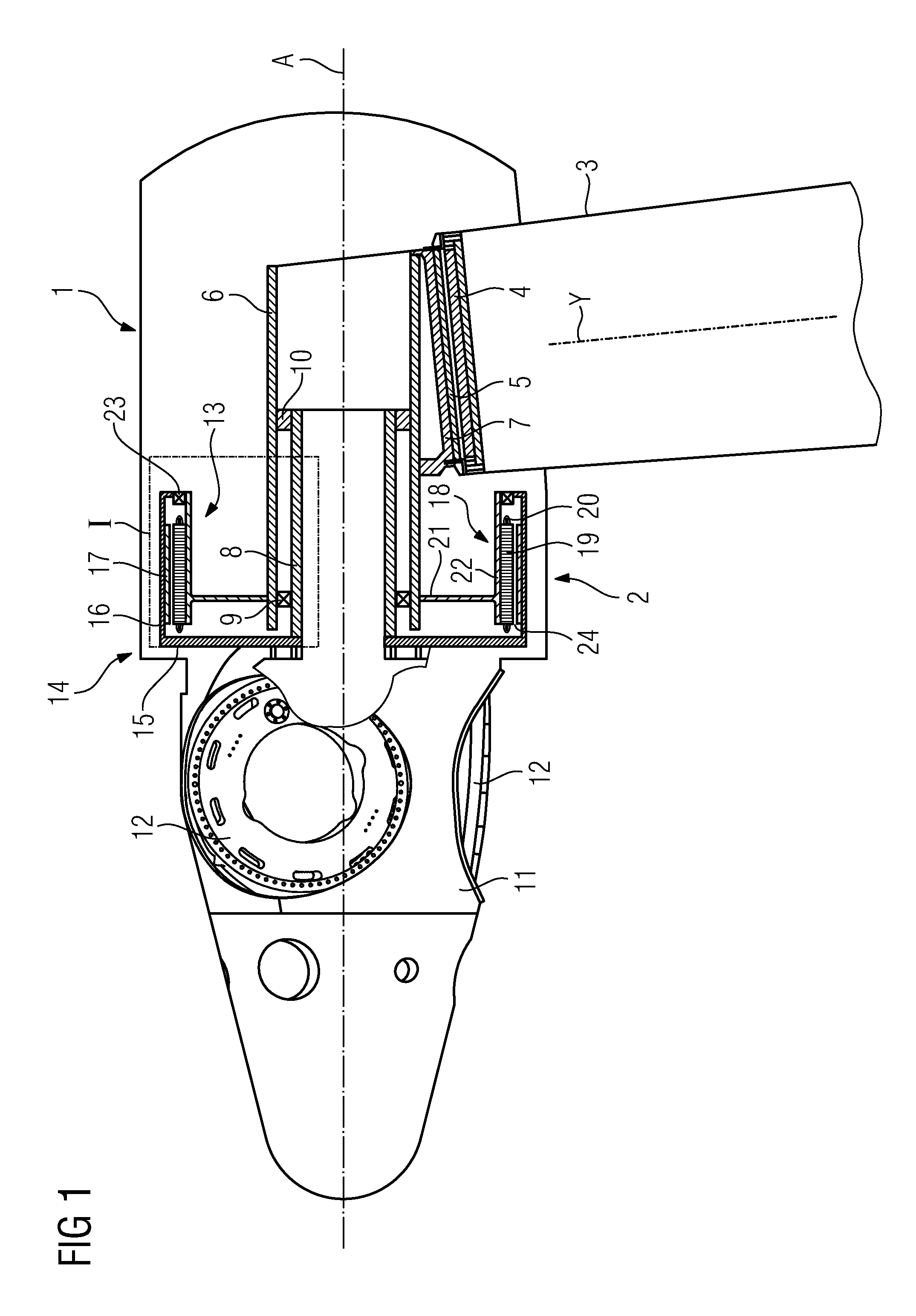
[0033]FIG. 1 shows schematically an embodiment of a first inventive wind turbine 1 comprising a direct drive generator 2 having a centre axis A which is arranged on the upwind side of a tower 3 of the wind turbine 1.

[0034]A tower flange 4 is arranged on the top of the tower 3. A bedplate 5 is attached to the tower flange 4. The wind turbine 1 comprises in a not explicitly shown manner a yaw system for turning the bedplate 5 of the wind turbine 1 around the axis Y of the tower 3 together with the other components of the wind turbine 1 which are directly or indirectly attached to the bedplate 5.

[0035]The wind turbine 1 comprises a stationary outer shaft 6. The rear side of the stationary outer shaft 6 is attached to a retaining arrangement 7 which is attached to the bedplate 5.

[0036]A rotatable inner shaft 8 is arranged inside the stationary outer shaft 6 and rotatably supported by two main bearings 9, 10 against the stationary outer shaft 6. A hub 11 is connected to the front end of ...


PUM


Abstract

A wind turbine is provided. The wind turbine includes a direct drive generator with a stator arrangement, a rotor arrangement substantially arranged around the stator arrangement and a longitudinal centre axis. The stator arrangement includes a stator support structure, which includes at least one substantially radial extending stator support element. The stator support element is attached to a substantially parallel to the centre axis extending stationary shaft, is substantially rigid in the radial direction and is at least partially in a certain extent flexible in the directions of the centre axis of the generator.

Description

CROSS REFERENCE TO RELATED APPLICATIONS[0001]This application claims priority of European Patent Office application No. 08014800.0 EP filed Aug. 20, 2008, which is incorporated by reference herein in its entirety.FIELD OF INVENTION[0002]The invention relates to a wind turbine comprising a direct drive generator.BACKGROUND OF INVENTION[0003]In principle there are two main types of wind turbines in view of the drive configuration of a wind turbine. The first type of a wind turbine is the more classical type of a wind turbine comprising a gearbox arranged between the main shaft and a generator of the wind turbine. The second type of a wind turbine is a gearless type comprising a direct drive or a directly driven generator. Such a direct drive generator can be made as a synchronous generator with winded rotor or with permanent magnets attached to the rotor, or it can be designed as an alternative type of a generator. Independently from the type of a direct drive generator it is desirabl...

Claims


Application Information

Patent Timeline
Patent Type & Authority Applications(United States)
IPC IPC(8): F03D9/00
CPCF03D1/001F03D11/00F03D11/04H02K7/1838H02K2201/03Y02E10/725Y02E10/728F05B2220/7066F03D13/10F03D13/20F03D15/20F03D80/00F03D80/70F03D80/88Y02E10/72
Inventor STIESDAL, HENRIK
Owner SIEMENS GAMESA RENEWABLE ENERGY AS
Why Eureka
Try Eureka