Common-mode choke coil

Active Publication Date: 2010-02-25
MURATA MFG CO LTD
View PDF8 Cites 17 Cited by
  • Summary
  • Abstract
  • Description
  • Claims
  • Application Information

AI Technical Summary

Benefits of technology

[0011]In view of the above, preferred embodiments of the present invention provide a common-mode choke coil which has induction immunity characteristics improved by a coil structure prev

Problems solved by technology

In such a case, the transmitter IC and the receiver IC malfunctio

Method used


Image

  • Common-mode choke coil
  • Common-mode choke coil
  • Common-mode choke coil

Examples


embodiment 1

Preferred Embodiment 1

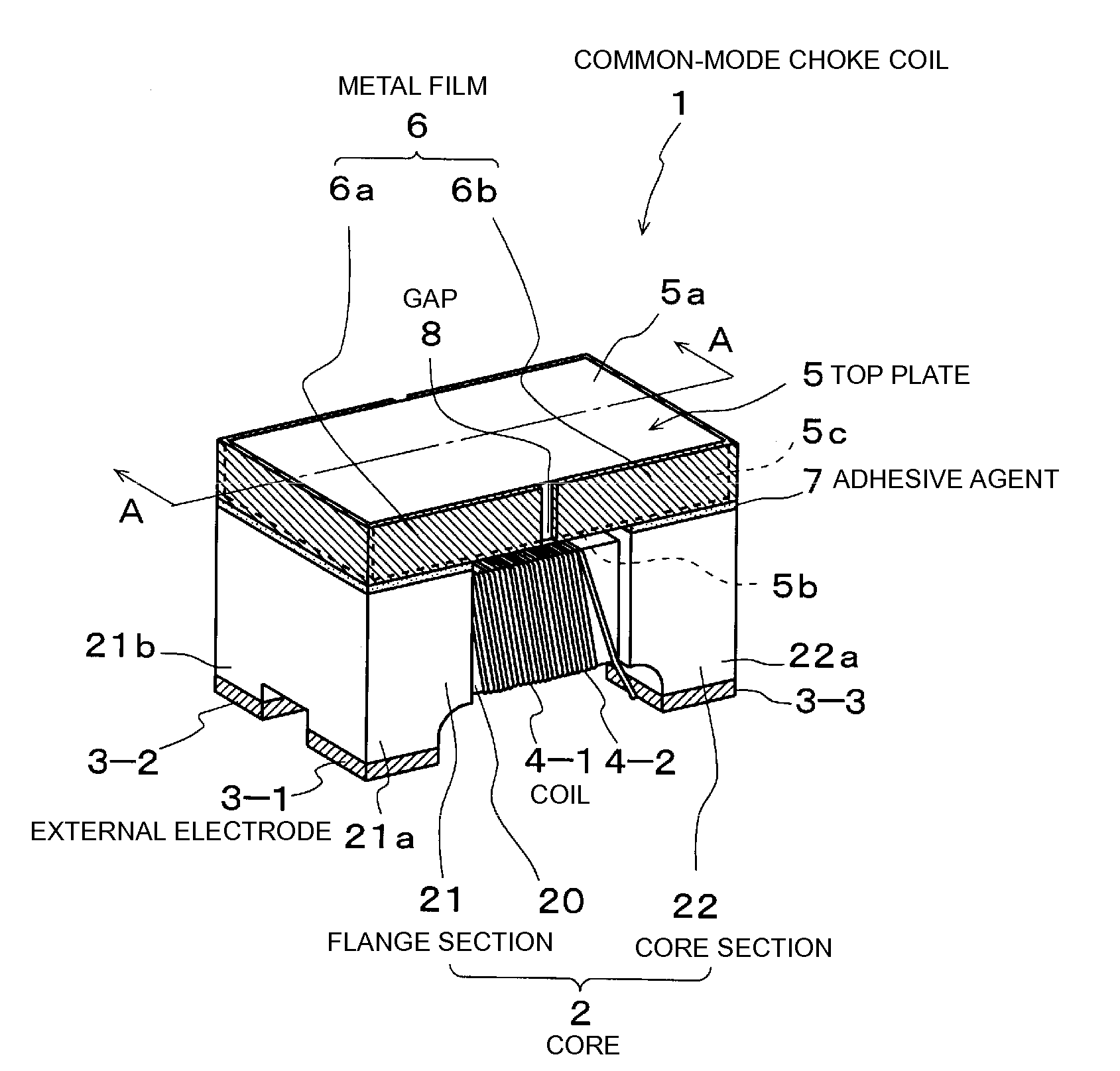
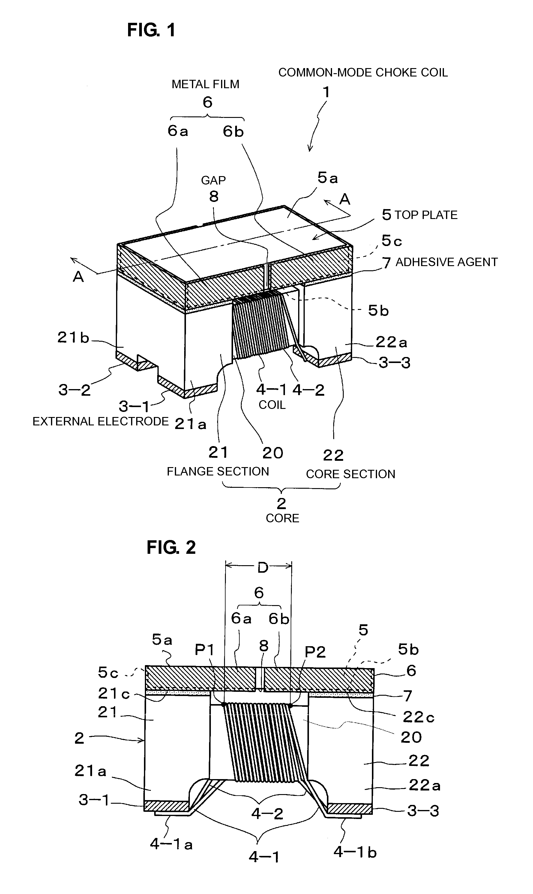
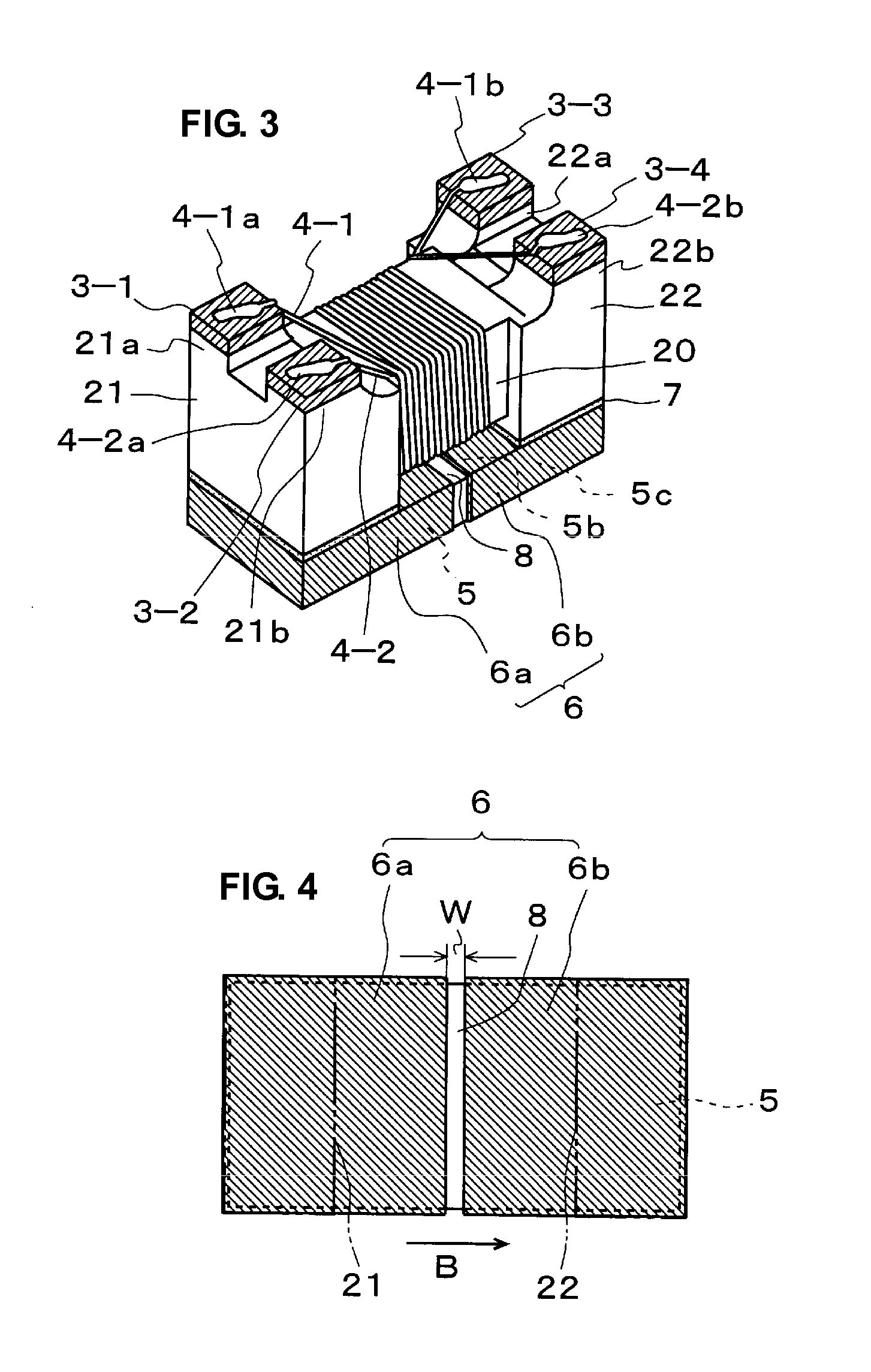
[0049]FIG. 1 is a perspective view illustrating a common-mode choke coil in accordance with one preferred embodiment of the present invention. FIG. 2 is a front view of the common-mode choke coil of the present preferred embodiment. FIG. 3 is a perspective view illustrating the underside of the common-mode choke coil.

[0050]The common-mode choke coil 1 is a wound-wire coil of surface-mount type, and includes, a core 2 as a magnetic core, four external electrodes 3-1 through 3-4, a pair of coils 4-1 and 4-2, and a top plate 5 as a magnetic plate as illustrated in FIGS. 1 and 2.

[0051]The core 2 is preferably made of ferrite such as Ni—Zn based ferrite, and includes a center core section 20 and a flange section 21 as a first flange and a flange section 21 as a second flange arranged at both ends of the core section 20.

[0052]The external electrodes 3-1 through 3-4 are arranged on the underside of the flange sections 21 and 22.

[0053]More specifically, the external el...


PUM


Abstract

A common-mode choke coil has induction immunity characteristics that are improved by a coil structure preventing a transmitter IC and a receiver IC from malfunctioning during an induction immunity test and which controls a decrease in ESD resistance and a decrease in self-resonance frequency. The common-mode choke coil includes a core, external electrodes, a pair of coils, and a top plate. The core includes a core section and a pair of flange sections. The pair of coils are wound around the core section of the core, and the ends of the coils are connected to the external electrodes, respectively. An underside and a side surface of the top plate are plated with a metal film, and bonded to the top surfaces of the flange sections preferably by an adhesive agent. The metal film is segmented into two separate portions so as to define two separate metal sections with a gap therebetween so that the metal sections are electrically disconnected.

Description

BACKGROUND OF THE INVENTION[0001]1. Field of the Invention[0002]The present invention relates to a winding-type common-mode choke coil for removing a common-mode noise on a transmission line.[0003]2. Description of the Related Art[0004]Techniques disclosed in Japanese Unexamined Patent Application Publication No. 2003-168611 and Japanese Unexamined Patent Application Publication No. 2000-133522 are currently available for a common-mode choke coil.[0005]The common-mode choke coil includes a core and two wires wound in a coil around a core section of the core. The core has flange sections at both ends thereof. The two ends of each of the coils are connected respectively to electrodes of the flange sections. A ferrite plate straddles the top sides of the flange sections.[0006]Such a structure of the common-mode choke coil removes the common-code noise entering a differential transmission line or the like.[0007]The known above-described common-mode choke coil has the following problem.[...

Claims


Application Information

Patent Timeline
IPC IPC(8): H01F27/29H01F27/30
CPCH01F17/045H01F2017/0093H01F27/34
Inventor NISHIKAWA, YOSHIEHIRAI, SHINYAAOKI, TAKAHIROMORINAGA, TETSUYAAZUMA, TAKAHIROSAITO, YASUSHIGOTO, YOSHIMASAISHIWATA, YU
Owner MURATA MFG CO LTD
Why Eureka
Try Eureka