Eureka AIR delivers breakthrough ideas for toughest innovation challenges, trusted by R&D personnel around the world.

Radio wave absorption material and radio wave absorber

Active Publication Date: 2010-02-25
HITACHI METALS LTD
View PDF13 Cites 3 Cited by
  • Summary
  • Abstract
  • Description
  • Claims
  • Application Information

AI Technical Summary

Benefits of technology

[0013]In consideration of the above-mentioned circumstances, the present invention is intended to provide a radio wave absorption material having high strength and high humidity stability and having performance equivalent to or better than that of the Ni—Cu—Zn-based ferrite sintered materials and to provide a radio wave absorber formed of the radio wave absorption material.
[0032]According to the present invention, it is possible to obtain an inexpensive radio wave absorption material having high strength and humidity stability and having radio wave absorption performance equivalent to or better than that of the Ni—Cu—Zn-based ferrite sintered bodies. Hence, a radio wave anechoic chamber having performance equivalent to or better than that of the conventional chambers can be set up at low cost by using the radio wave absorber produced using this radio wave absorption material.

Problems solved by technology

Since NiO being expensive among main materials for use in ferrite is used in such Ni—Cu—Zn-based ferrite sintered materials, there occurs a problem that Ni—Cu—Zn-based ferrite tiles produced as radio wave absorbers are high in cost.
However, since radio wave absorbers, in which the Mn—Zn-based ferrite sintered materials described in Patent documents 6 and 7 are used, have insulating phases formed of CaO, etc. in grain boundaries, intergranular failure is apt to occur, and the strength of the ferrite materials is lowered.
In the case that the strength of the ferrite materials is low, sintered bodies are apt to be broken when they are cut or assembled, whereby not only low yield is caused but also there is a problem that they are difficult to use as radio wave absorbers for use in radio wave anechoic chambers.
Furthermore, there is a problem that the change in dielectric constant with respect to humidity is significant due to water absorption in the grain boundary phases formed of CaO.

Method used


Image

  • Radio wave absorption material and radio wave absorber
  • Radio wave absorption material and radio wave absorber
  • Radio wave absorption material and radio wave absorber

Examples


Embodiment Construction

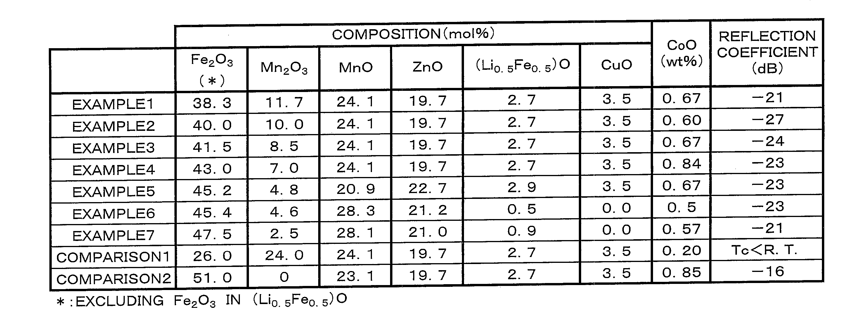
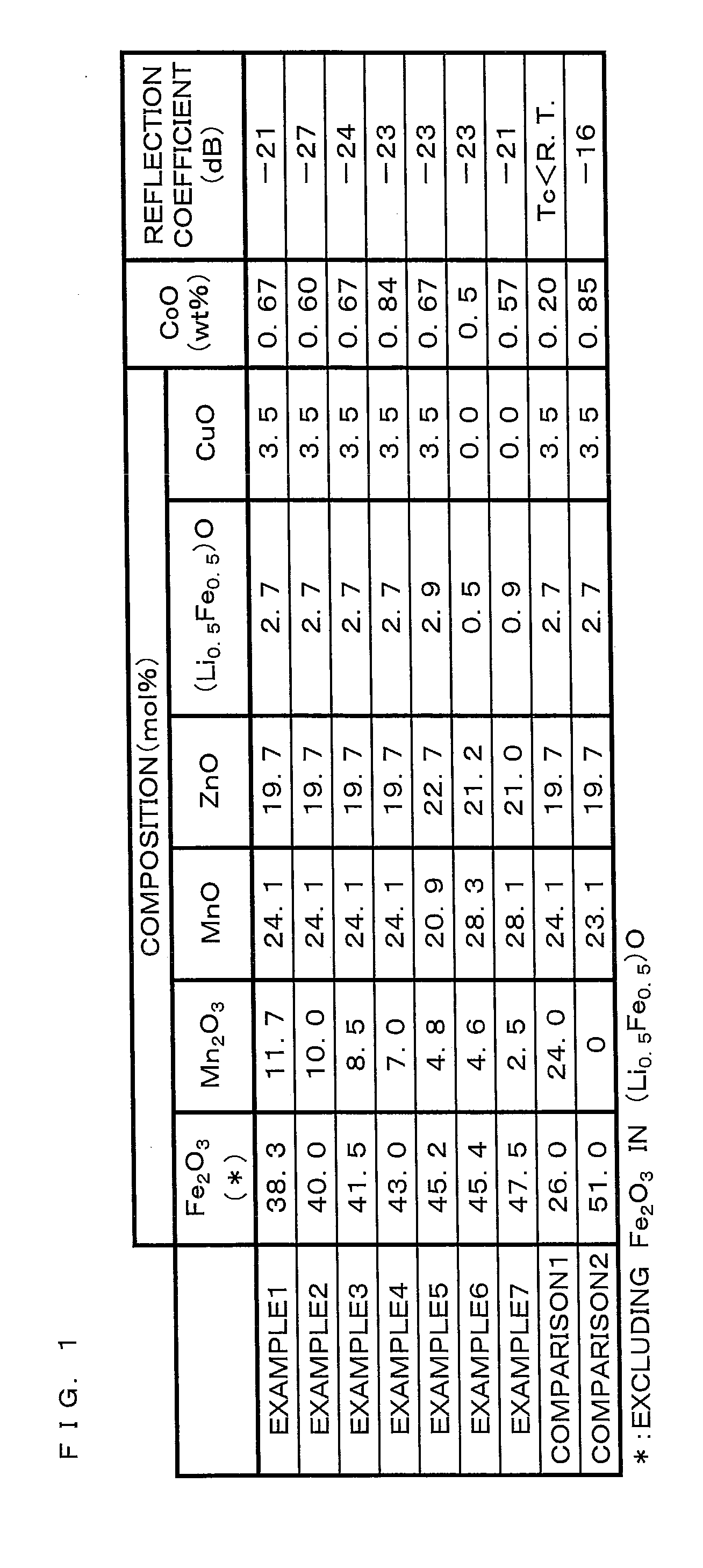
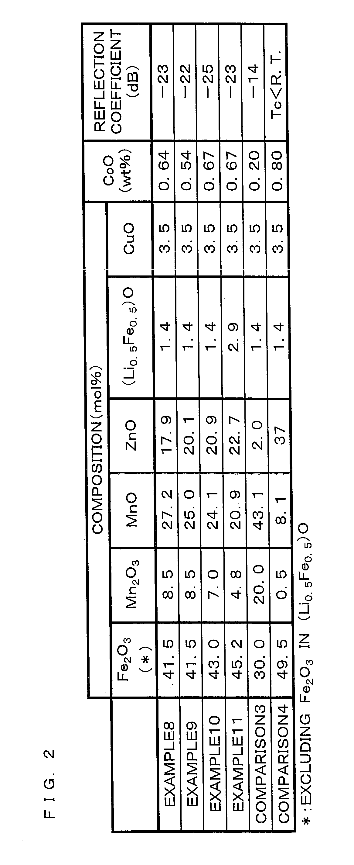
[0044]A radio wave absorption material according to the present invention is obtained by adjusting components Fe, Mn, Zn and Li serving as main components so as to have ratios in terms of the respective oxides, that is, Fe2O3: to 49.5 mol %, Mn2O3: 0.5 to 20 mol %, ZnO: 5 to 35 mol %, (Li0.5Fe0.5)O: 0.2 to 15 mol % and MnO: the rest, by adding CoO: 0.1 to 2 wt % and by performing firing to form a ferrite compact.

[0045]Part of ZnO may be replaced with 20 mol % or less of CuO in the composition of the above-mentioned main components.

[0046]The reason why the composition values of the respective oxides are restricted will be described below.

(Fe2O3: 30 to 49.5 mol %)

[0047]In the Case that F2O3 is Less than 30 Mol %, the Material is not Practical since Tc (Curie temperature) lowers. On the other hand, in the case that Fe2O3 is more than 49.5 mol %, the specific resistance of the material lowers, whereby the dielectric constant thereof increases and the radio wave absorption performance th...


PUM

PropertyMeasurementUnit
Thicknessaaaaaaaaaa
Frequencyaaaaaaaaaa
Sound / signal amplitudeaaaaaaaaaa

Abstract

A radio wave absorption material is characterized to be obtained by firing a ferrite material that is formed by adding an accessory component, 0.1 to 2 wt % of CoO, to an oxide magnetic material containing main components, 30 to 49.5 mol % of Fe2O3, 0.5 to 20 mol % of Mn2O3, 5 to 35 mol % of ZnO, 0.2 to 15 mol % of (Li0.5Fe0.5)O and MnO as the rest. In the above-mentioned composition, part of ZnO may be replaced with 20 mol % or less of CuO. This radio wave absorption material has high strength and humidity stability and has excellent radio wave absorption performance although low in cost.

Description

[0001]This application is the national phase Linder 35 U.S.C. §371 of PCT International Application No. PCT / JP2007 / 070319 which has an International filing date of Oct. 18, 2007 and designated the United States of America.BACKGROUND[0002]1. Technical Field[0003]The present invention relates to a radio wave absorption material formed of a sintered ferrite material for absorbing unnecessary radio waves and to a radio wave absorber formed of the radio wave absorption material.[0004]2. Description of Related Art[0005]With the development of communication technology and radio guidance technology for airplanes, etc. or with the proliferation of various electric / electronic appliances, such as television sets, radios and mobile phones, for use in prevention of malfunctions in controllers, for use in noise filters for various electric / electronic appliances, for use in radio wave absorption walls or for use in radio wave anechoic chambers, radio wave absorbers matching with the respective fre...

Claims


Application Information

Patent Timeline
IPC IPC(8): H01Q17/00
CPCC04B35/2658H05K9/0075C04B2235/3208C04B2235/3217C04B2235/3241C04B2235/3262C04B2235/3265C04B2235/3274C04B2235/3275C04B2235/3279C04B2235/3281C04B2235/3284C04B2235/3418C04B2235/444C04B2235/447C04B2235/448C04B2235/6562C04B2235/658C04B2235/77C04B2235/786C04B2235/96H01F1/344H01F1/36C04B2235/3203C04B35/26H01F1/00H01F1/34H05K9/00
Inventor ITOH, SHINROHMIYOSHI, YASUHARU
Owner HITACHI METALS LTD
Why Eureka
Eureka Blog
Learn More