Wireless communication apparatus and wireless communicating method
a wireless communication and wireless communication technology, applied in multiplex communication, diversity/multi-antenna systems, baseband system details, etc., can solve problems such as inability to achieve directionality and lost setting at the transmitting uni
- Summary
- Abstract
- Description
- Claims
- Application Information
AI Technical Summary
Benefits of technology
Problems solved by technology
Method used
Image
Examples
first embodiment
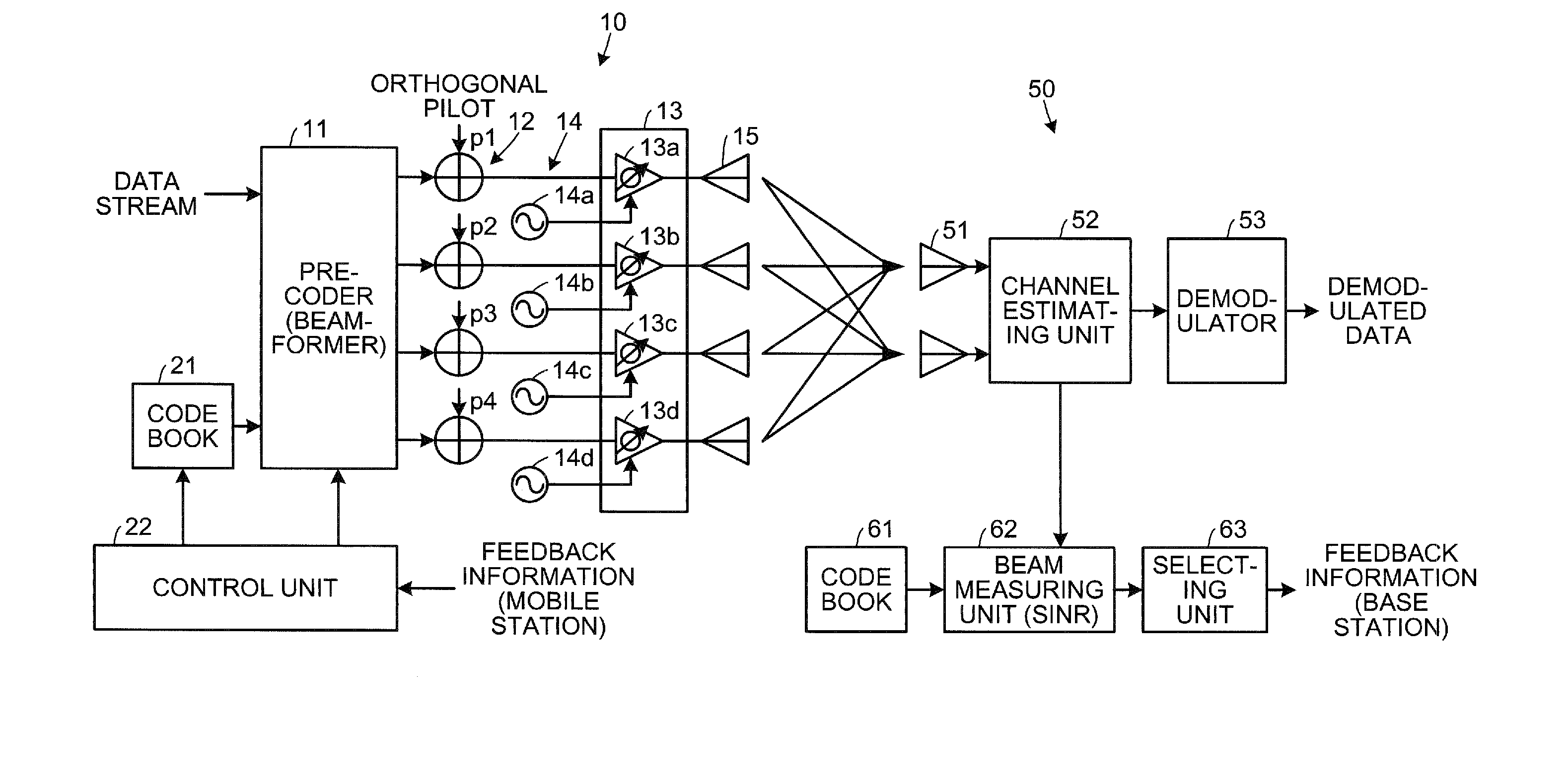
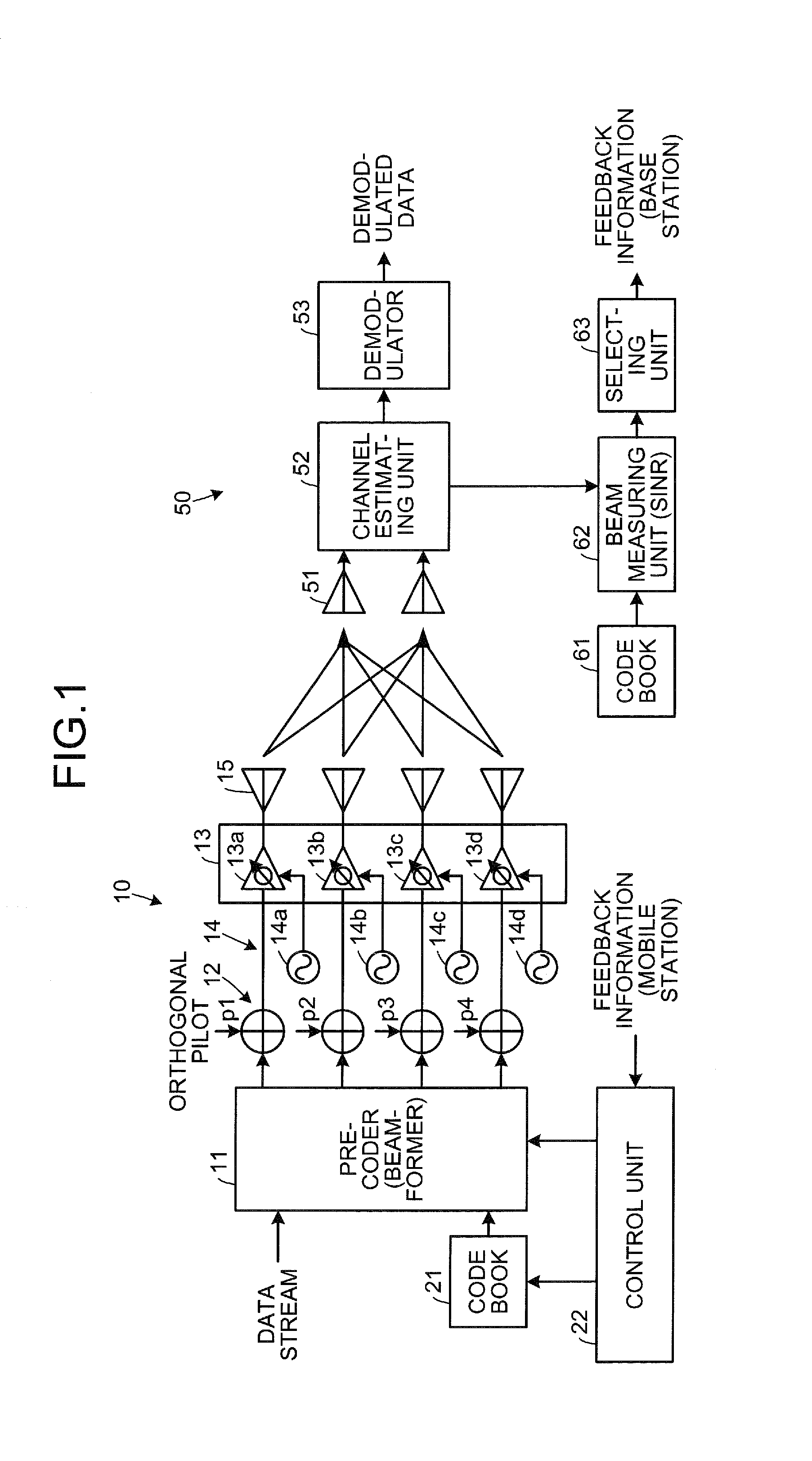
[0039]FIG. 1 is a diagram of a configuration of a wireless communication apparatus according to a FIG. 1 depicts a wireless communication apparatus 10 of a base station (transmitting side) and a wireless communication apparatus 50 of a mobile station (receiving side) in a mobile communication system.
[0040]Data (a data stream) for multiple systems (four systems in FIG. 1) is input into a pre-coder 11 and phase adjustments of given amounts are made for each of the systems to form a multi-beam. A code book 21 is configured to store therein 16 correction values (corresponding to the number of combinations of the systems), weights given to the data of each of the systems.
[0041]An adding unit 12 adds a pilot signal of a quadrature component (a quadrature pilot) to the data output for each system from the pre-coder 11. A transmitting unit 13 includes transmitting circuits 13a to 13d respectively for the systems, modulates the data at an oscillation frequency (RF) of an oscillator 14 (14a ...
second embodiment
[0066]FIG. 8 is a timing chart of transitions of search states. In the second embodiment, the wireless communication apparatus 50 of the mobile station also executes the same processes as those depicted in FIG. 3. The processes are also identical in that, after a search of the entire code book 61 in the mobile station (step S11) is executed, the search of a portion (step S12) is executed.
[0067]In the second embodiment, the oscillator 14 is configured to supply the common local signal to the transmitting unit 13 and no variation in phase is occurs among the systems. Therefore, the entire code book 61 is searched once when the calibration process is executed once. After the search of the entire code book 61 is executed once, the time period for the search of the portion may be increased compared to that of the first embodiment (the relative length of the time period for the search of the portion may be increased). The search of the entire code book 61 may be executed at predetermined ...
third embodiment
[0086]After the calibration has been completed in this manner, the mobile station searches a portion of the code book (step S112). In the third embodiment, because the calibration phase correction is executed by the base station such that the center of the matrix selection distribution coincides with the position of the fundamental matrix, the mobile station merely searches for the beam number in the fundamental matrix. In the example depicted in FIG. 10, the beam number “3” is reported to the base station, as the result of the search.
[0087]Subsequently, the base station executes data transmission (step S106). In this case, the data transmission is executed using the fundamental matrix and the beam number that is reported by the mobile station; thereby, one session of the processes comes to an end.
[0088]FIG. 15 is a diagram of a first measurement example of the matrix selection distribution by the phase estimating unit. The phase estimating unit 31 measures the matrix selection dist...
PUM
 Abstract
Description
Claims
Application Information
 - R&D
- Intellectual Property
- Life Sciences
- Materials
- Tech Scout
- Unparalleled Data Quality
- Higher Quality Content
- 60% Fewer Hallucinations
Browse by: Latest US Patents, China's latest patents, Technical Efficacy Thesaurus, Application Domain, Technology Topic, Popular Technical Reports.
© 2025 PatSnap. All rights reserved.Legal|Privacy policy|Modern Slavery Act Transparency Statement|Sitemap|About US| Contact US: help@patsnap.com


