Biosensor device and method for detecting molecules in an analyte

a biosensor and analyte technology, applied in the direction of chemiluminescene/bioluminescence, instruments, material analysis, etc., can solve the problems of high production and operating costs of this biosensor device, high measurement principle and design complexity, and achieve the effect of simple detection principle and high sensitiveness

Inactive Publication Date: 2010-02-25
KONINKLIJKE PHILIPS ELECTRONICS NV
View PDF2 Cites 6 Cited by
  • Summary
  • Abstract
  • Description
  • Claims
  • Application Information

AI Technical Summary

Benefits of technology

[0008]It is an object of the present invention to provide a biosensor device for detecting molecules in an analyte which allows for a very simple detection principle and which is highly sensitive to various species of molecules.

Problems solved by technology

Its is a disadvantage of this biosensor device, that the measurement principle as well as the design of this biosensor device are highly complicated, since much technical effort is required to realize this kind of interferometry measurement as well as the conversion and analysis of the output signal.
Therefore the production and operating costs of this biosensor device are high compared to a biosensor device that is based on a simple detection mechanism.
In addition, it is a disadvantage of this biosensor device, that a quantitative analysis of bound molecules is rather sophisticated, as there is no direct correlation between the amount of bound molecules and the phase difference of the light measured in the Mach-Zehnder interferometry configuration.
Thus further measurements of e.g. the oscillation frequency of receptor molecules with and without bound molecules are required causing additional technical effort for realizing such measurements.
Moreover, it is a disadvantage, that this biosensor device is limited to few specific applications, since the receptor molecules are limited to few specific species of molecules to be detected.

Method used


Image

  • Biosensor device and method for detecting molecules in an analyte
  • Biosensor device and method for detecting molecules in an analyte
  • Biosensor device and method for detecting molecules in an analyte

Examples


Embodiment Construction

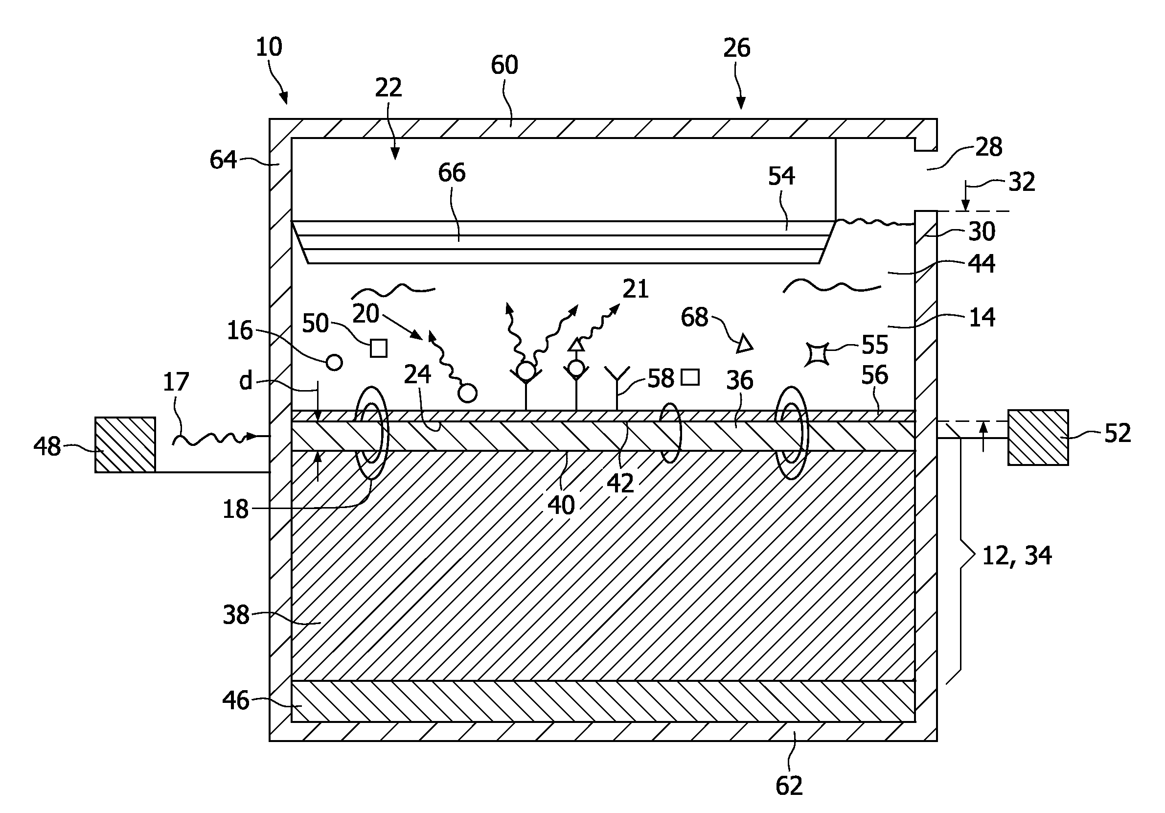
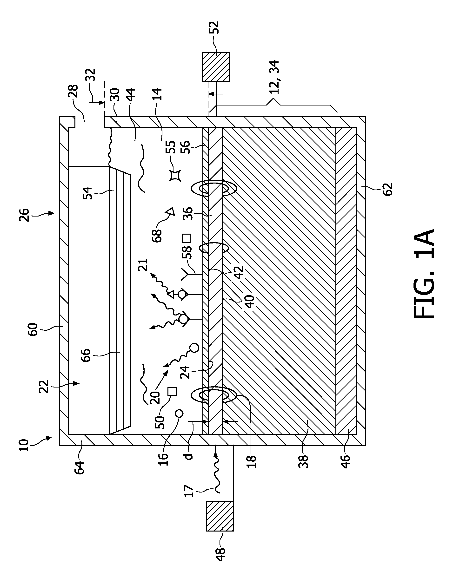
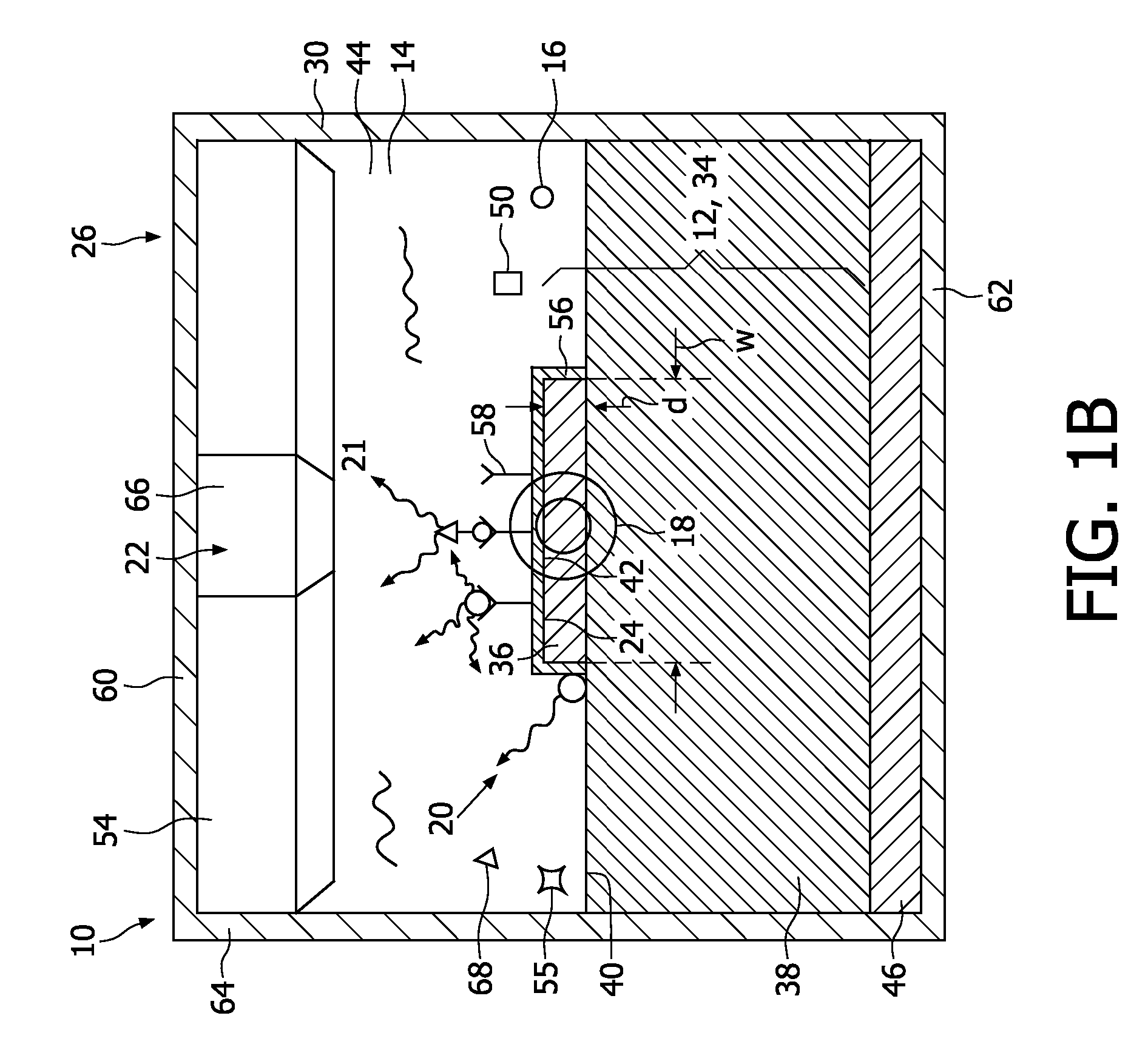
[0061]FIGS. 1A and 1B show a biosensor device 10 in a schematic representation. The biosensor device 10 is used to detect molecules such as biomolecules like DNA in an analyte, where the detection sensitivity of the biosensor device 10 can be increased based on the magnetic or electric properties of the molecules to be detected.

[0062]According to the invention, the term “molecules” generally refers to molecules, beads and particles which are comprised in the analyte.

[0063]The biosensor device 10 comprises a binding element 12 that can be brought into contact with the analyte 14 for binding the molecules 16 in the analyte 14. Diffusion causes the molecules in the analyte 14 to move towards and away from the binding element 12 for binding to the binding element 12. Light 17 is applied to the binding element 12 providing excitation light 18 for the molecules 16 located around the binding element 12, as the excitation light 18 is concentrated around the binding element 12. Upon binding ...


PUM

PropertyMeasurementUnit
refractive indices n1aaaaaaaaaa
thicknessaaaaaaaaaa
thicknessaaaaaaaaaa

Abstract

A biosensor device (10) for detecting molecules (16) in an analyte (14) comprises a binding element (12) which can be brought into contact with the analyte (14) for binding the molecules (16) thereto. The binding element (12) is an optical waveguide (34) comprising a strip (36) on a first layer (38). Light (17) can be applied to the strip (36). The biosensor device (10) further comprises an optical detection system (22) for detecting luminescent light (20) emitted by the excited molecules (16).

Description

FIELD OF THE INVENTION[0001]The invention relates to a biosensor device for detecting molecules in an analyte.[0002]The invention further relates to a method for detecting molecules in an analyte.[0003]In general, a biosensor device is used to detect molecules in an environment by means of binding the molecules to the binding element of the biosensor device and measuring a change in chemical or physical properties of the biosensor device. In this way, the binding element is directly exposed to the environment of the biosensor device, e.g. to air or to an analyte comprising the molecules.BACKGROUND OF THE INVENTION[0004]A biosensor device for detecting molecules in an analyte is known from US 2006 / 0045809 A1 that comprises a binding element designed as optical waveguide with a strip arranged on a substrate in a Mach-Zehnder interferometry configuration. The waveguide can be supplied with light, when the analyte is brought into contact with the binding element. The biosensor device fu...

Claims


Application Information

Patent Timeline
Patent Type & Authority Applications(United States)
IPC IPC(8): G01N21/76G01N33/50
CPCG01N33/54373G01N21/648
Inventor KLUNDER, DERK JAN WILFREDVAN HERPEN, MAARTEN MARINUS JOHANNES WILHELMS
Owner KONINKLIJKE PHILIPS ELECTRONICS NV
Why Eureka
Try Eureka