Variable Slope Exhaust Nozzle

a technology of exhaust nozzle and variable slope, which is applied in the direction of rocket engine plants, machines/engines, engine manufacture, etc., can solve the problems of correspondingly reducing aerodynamic performance and efficiency of nozzles, and achieve the effect of improving efficiency

Active Publication Date: 2010-03-04
GENERAL ELECTRIC CO
View PDF27 Cites 33 Cited by
  • Summary
  • Abstract
  • Description
  • Claims
  • Application Information

AI Technical Summary

Benefits of technology

[0012]Accordingly, it is desired to provide an exhaust nozzle having...

Problems solved by technology

However, the introduction of the upper and lower bifurcations correspondingly affects the circumferential continuity of the velocity...

Method used


Image

  • Variable Slope Exhaust Nozzle
  • Variable Slope Exhaust Nozzle
  • Variable Slope Exhaust Nozzle

Examples


Embodiment Construction

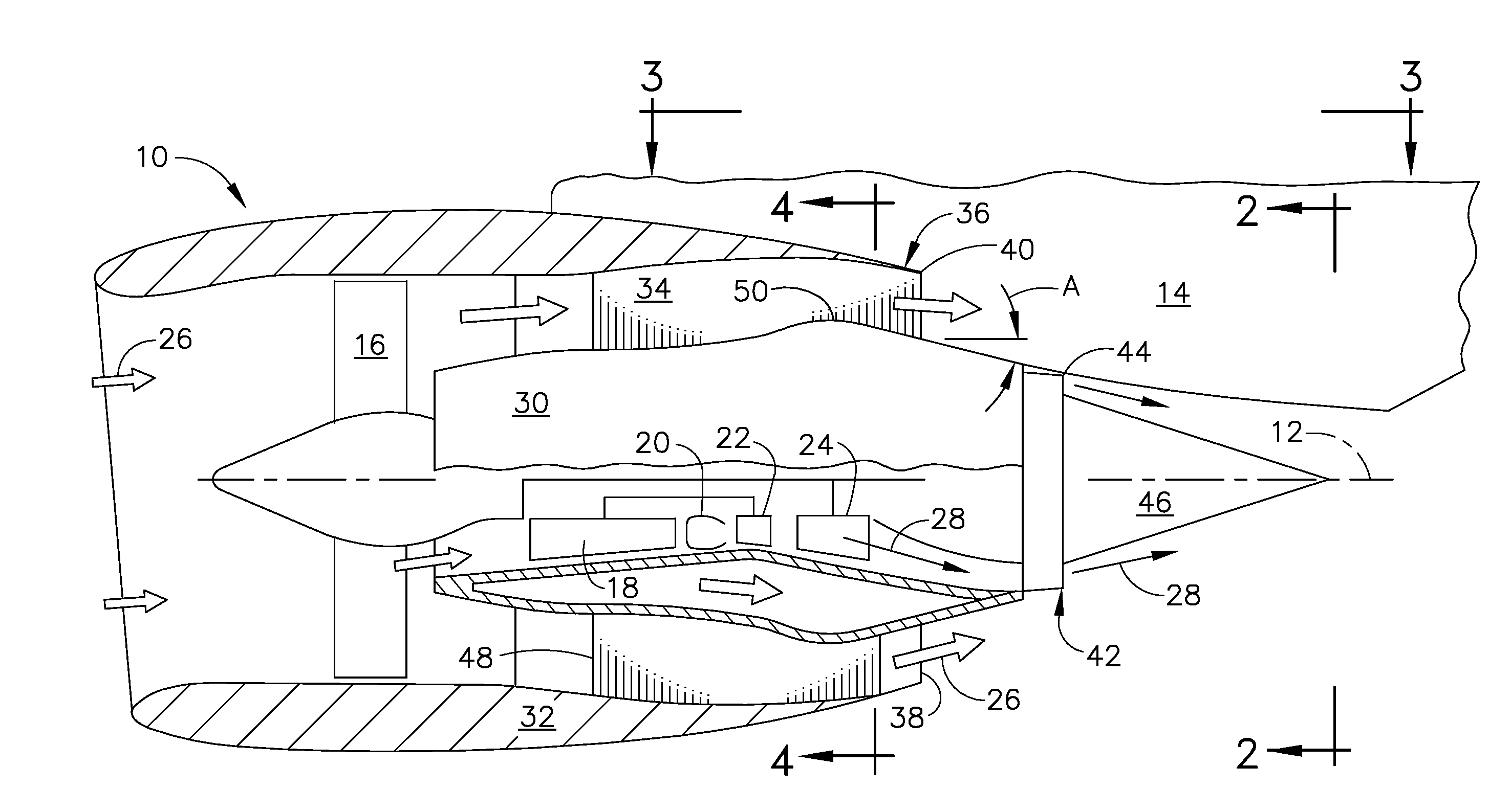
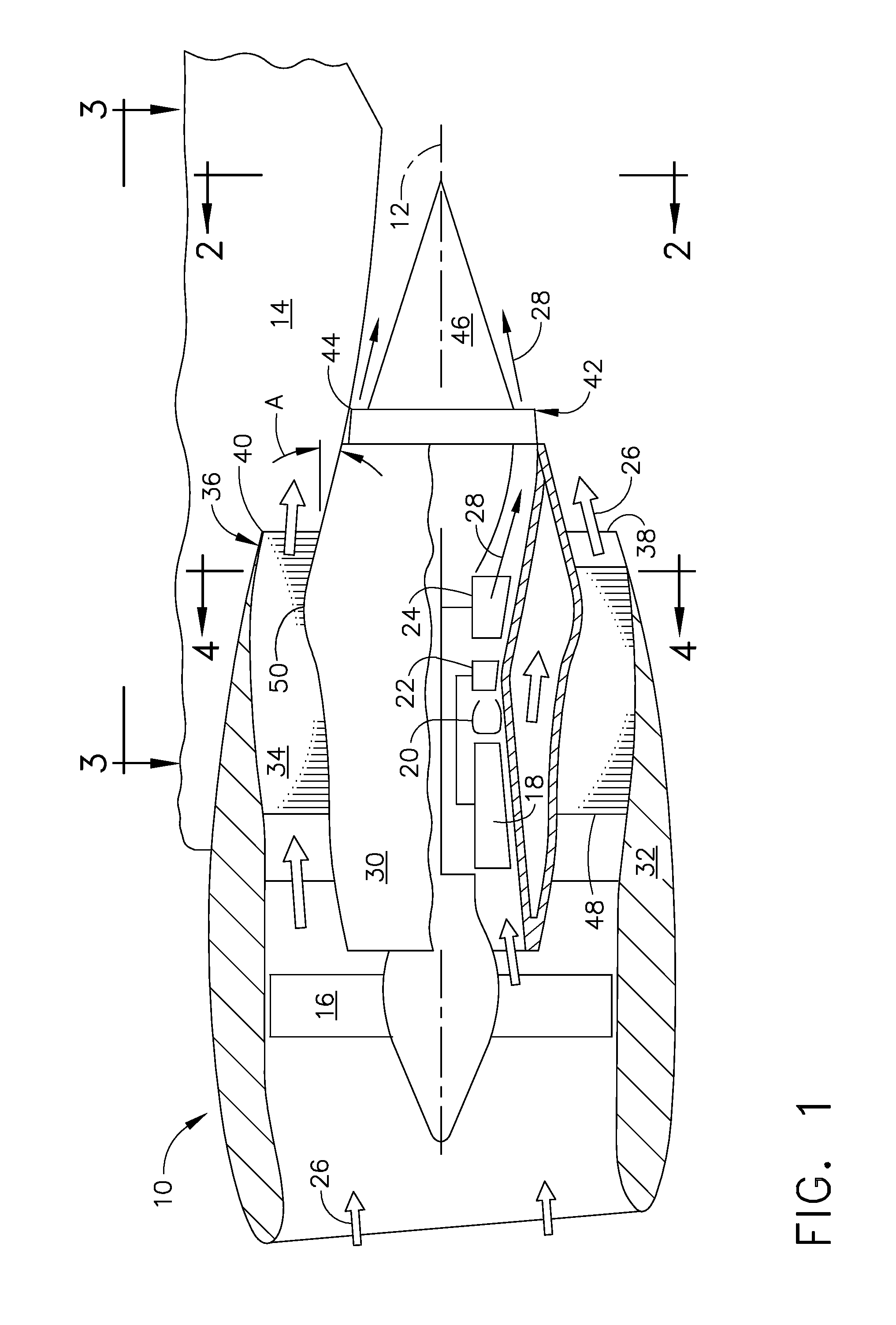
[0021]Illustrated schematically in FIG. 1 is turbofan aircraft gas turbine engine 10 which is generally axisymmetrical about an a longitudinal or axial centerline axis 12. The engine is specifically configured for being suspended vertically by a pylon 14 to the wing of aircraft for powering the aircraft during flight.

[0022]The engine includes in serial flow communication a fan 16, compressor 18, combustor 20, high pressure turbine (HPT) 22, and low pressure turbine (LPT) 24. The rotors of the HPT 22 are joined by one shaft to the rotors of the compressor 18, and the rotors of the LPT 24 are joined by a second shaft to the rotor supporting the fan blades in the fan 16.

[0023]During operation, ambient air 26 enters the inlet of the engine and is pressurized in part by the fan 16, with an inner portion of the pressurized air then being channeled through the compressor 18 which further pressurizes the air which is then mixed with fuel in the combustor 20 for generating hot combustion gas...


PUM


Abstract

A turbine exhaust nozzle includes an inner shell disposed coaxially inside an outer shell to define a flow duct terminating in an outlet at a trailing edge of the outer shell. The inner shell is non-axisymmetric and varies in axial slope angle circumferentially around the duct.

Description

BACKGROUND OF THE INVENTION[0001]The present invention relates generally to gas turbine engines, and, more specifically, to exhaust nozzles in turbofan aircraft engines.[0002]In a gas turbine engine, air is pressurized in a compressor and mixed with fuel in a combustor for generating hot combustion gases from which energy is extracted in turbine stages. A high pressure turbine (HPT) follows the combustor and extracts energy from the combustion gases for powering the compressor. A low pressure turbine (LPT) follows the HPT and extracts additional energy from the gases for powering an upstream fan in an exemplary turbofan aircraft engine application.[0003]Modern turbofan aircraft engines have undergone decades of continuing development for maximizing aerodynamic efficiency while minimizing weight thereof, and for also achieving long useful life. Engine efficiency may be simply evaluated by specific fuel consumption (SFC) in which fractionally small improvements thereof are significant...

Claims


Application Information

Patent Timeline
IPC IPC(8): F02K1/00
CPCB64D33/04F02K3/06F05D2250/14F02K1/52F05D2250/231F02K1/08F02K3/04F02K9/86F02K3/02
Inventor DINDAR, MUSTAFABURTON, SCOTT ANDREWJAMES BLODGETT, KEITH EDWARDCEDAR, RICHARD DAVID
Owner GENERAL ELECTRIC CO
Why Eureka
Try Eureka