Horizontal articulated robot

a robot and horizontal technology, applied in the field of horizontal robots, can solve the problems of deteriorating responsiveness to movement and positioning precision, difficult to reduce the minimum radius rmin, and restricted miniaturization of the arm frame, so as to achieve the effect of reducing the increase in mass

Active Publication Date: 2010-03-04
SEIKO EPSON CORP
View PDF14 Cites 33 Cited by
  • Summary
  • Abstract
  • Description
  • Claims
  • Application Information

AI Technical Summary

Benefits of technology

[0012]A horizontal articulated robot according to an aspect of the invention includes a base, a first arm provided rotatably around a first rotation axis on the base, a second arm provided rotatably around a second rotation axis on the first arm, the second rotation axis being parallel to the first rotation axis, and a main shaft provided in the second arm to be extended in a direction parallel to the second rotation axis, a distance between the second rotation axis and the main shaft being shorter than a length of a straight line connecting the first and the second rotation axes, and the first arm having a recessed portion formed so as to include a position on a rotation path where a rotation radius around the second rotation axis is equivalent to the distance between the second rotation axis and the main shaft.
[0013]In the horizontal articulated robot, the main shaft has the rotation path where the rotation radius around the second rotation axis is equivalent to the length of the second arm. The main shaft is movable to be positioned in such a manner that the main shaft enters into an eccentrically recessed region of the first arm. In other words, the movable range of the main shaft is extended by an amount of reduction in a minimum rotation radius with respect to the first rotati

Problems solved by technology

Accordingly, miniaturization of the arm frame is restricted, and it is thus difficult to reduce th

Method used


Image

  • Horizontal articulated robot
  • Horizontal articulated robot
  • Horizontal articulated robot

Examples


Embodiment Construction

[0043]Embodiments of the invention will be described with reference to the drawings. Hereinafter, a horizontal articulated robot according to a first embodiment of the invention will be described in detail.

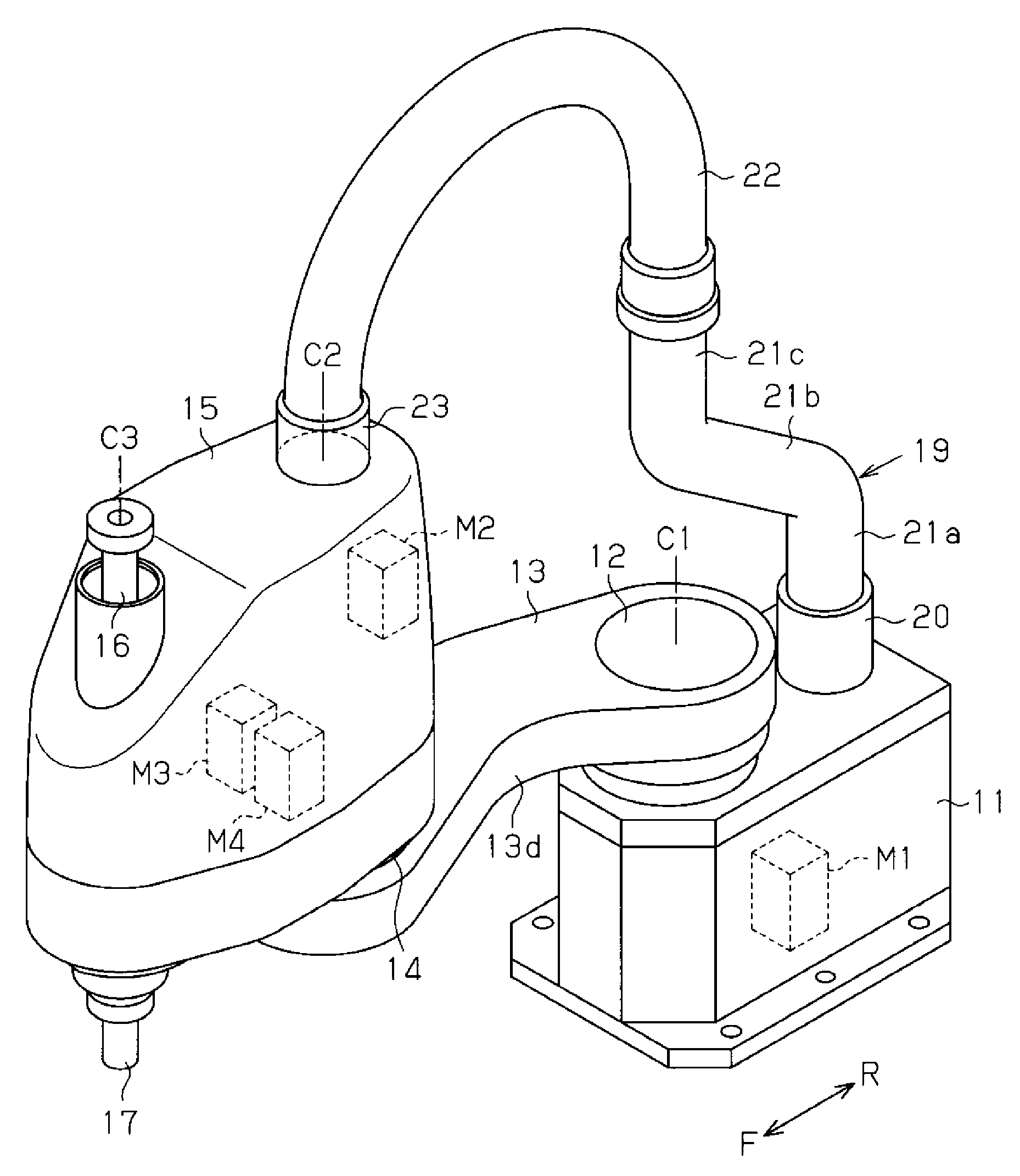
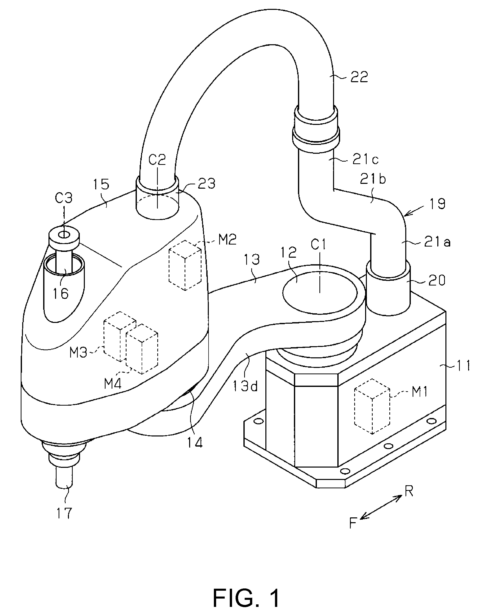
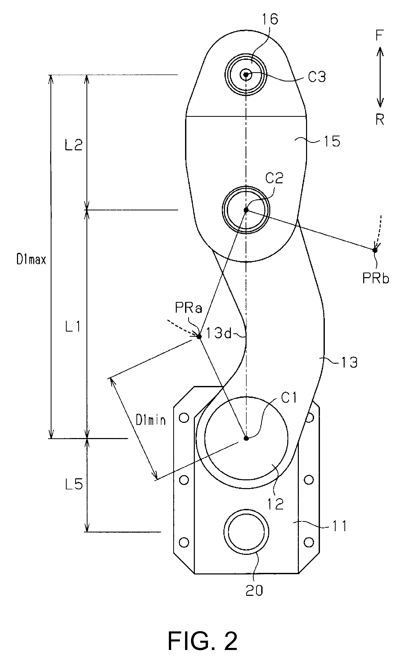
[0044]FIG. 1 shows a perspective structure of the horizontal articulated robot (a SCARA robot). FIG. 2 shows a top-surface structure of the SCARA robot.

[0045]As shown in FIG. 1, the SCARA robot includes a base 11 as a supporting member disposed on a floor or the like. At an upper end portion of the base 11 is provided a connection shaft 12 that rotatably supports a base end portion of a first arm 13, as a rotating member. The connection shaft 12 is formed in a cylindrical shape with an axial center C1 and is provided rotatably around the axial center C1 on the base 11. The connection shaft 12 is rotated forward or backward by a first motor M1 provided in the base 11. Thereby, the first arm 13 rotates around the axial center C1 of the connection shaft 12 rotated by the first motor ...


PUM


Abstract

A horizontal articulated robot includes a base, a first arm provided rotatably around a first rotation axis on the base, a second arm provided rotatably around a second rotation axis on the first arm, the second rotation axis being parallel to the first rotation axis, and a main shaft provided in the second arm to be extended in a direction parallel to the second rotation axis. A distance between the second rotation axis and the main shaft is shorter than a length of a straight line connecting the first and the second rotation axes. Additionally, the first arm has a recessed portion formed so as to include a position on a rotation path where a rotation radius around the second rotation axis is equivalent to the distance between the second rotation axis and the main shaft.

Description

BACKGROUND[0001]1. Technical Field[0002]The present invention relates to an industrial robot, and more particularly to a horizontal articulated robot having a plurality of horizontally rotating arms.[0003]2. Related Art[0004]Among industrial robots, there is known a SCARA robot (a horizontal articulated robot) with a plurality of arms sequentially connected by means of a horizontal articulation. FIG. 12 shows an example of a planar structure of a common SCARA robot having two arms.[0005]As shown in FIG. 12, the SCARA robot includes a base 51, a first arm 52 having a base end portion horizontally rotatably connected to a base 51, and a second arm 53 having a base end portion connected to an extreme end portion of the first arm 52 by a horizontal articulation.[0006]FIG. 13 shows an outline of a movable range in the SCARA robot thus structured. As in the drawing, the first and the second arms 52 and 53 work together to move a working portion 53a disposed at an extreme end portion of th...

Claims


Application Information

Patent Timeline
IPC IPC(8): B25J18/00
CPCB25J9/044Y10T74/20311Y10T74/20305B25J18/005
Inventor ONO, MASATOSHIMEYERHOFF, CHRISTOPH
Owner SEIKO EPSON CORP
Why Eureka
Try Eureka