Dump truck

a dump truck and electric motor technology, applied in the direction of engine-driven generators, motor/generator/converter stoppers, process and machine control, etc., can solve the problems of increasing the noise level inside the cab, and increasing the size of resistor boxes, etc., to achieve easy propagation, increase the noise level inside the cab, and large in size

Active Publication Date: 2010-03-04
NIHON KENKI CO LTD +1
View PDF31 Cites 21 Cited by
  • Summary
  • Abstract
  • Description
  • Claims
  • Application Information

AI Technical Summary

Benefits of technology

[0008]Moreover, the noise of the cooling fans inside the resistor boxes is easily propagated into the cab, which increases the noise level inside the cab, because the cooling fans are large in size and thus produce a high level of noise and also because the front sections of the resistor boxes protrude up to a position where the front sections and the cab are positioned in the same lateral direction when viewed from the cab. Hence, there is a growing demand for the above issues to be addressed.
[0009]The present invention has been contrived to address the above issues, and one of the objects of the invention is to provide an electrically-driven dump truck with improved side visibility from its cab.
[0010]Another is to provide an electrically-driven dump truck with a reduced noise level inside the cab.

Problems solved by technology

In the case of a giant dump truck, the capacity of its resistors that consume regenerative electric power often needs to be increased greatly for the purpose of increasing its dynamic braking force, which results in an increase in the size of its resistor boxes.
This arrangement of the resistor boxes impairs side visibility from the cab because the front sections of the resistor boxes protrude in an anterior direction of the truck.
Moreover, the noise of the cooling fans inside the resistor boxes is easily propagated into the cab, which increases the noise level inside the cab, because the cooling fans are large in size and thus produce a high level of noise and also because the front sections of the resistor boxes protrude up to a position where the front sections and the cab are positioned in the same lateral direction when viewed from the cab.

Method used


Image

  • Dump truck
  • Dump truck
  • Dump truck

Examples


first embodiment

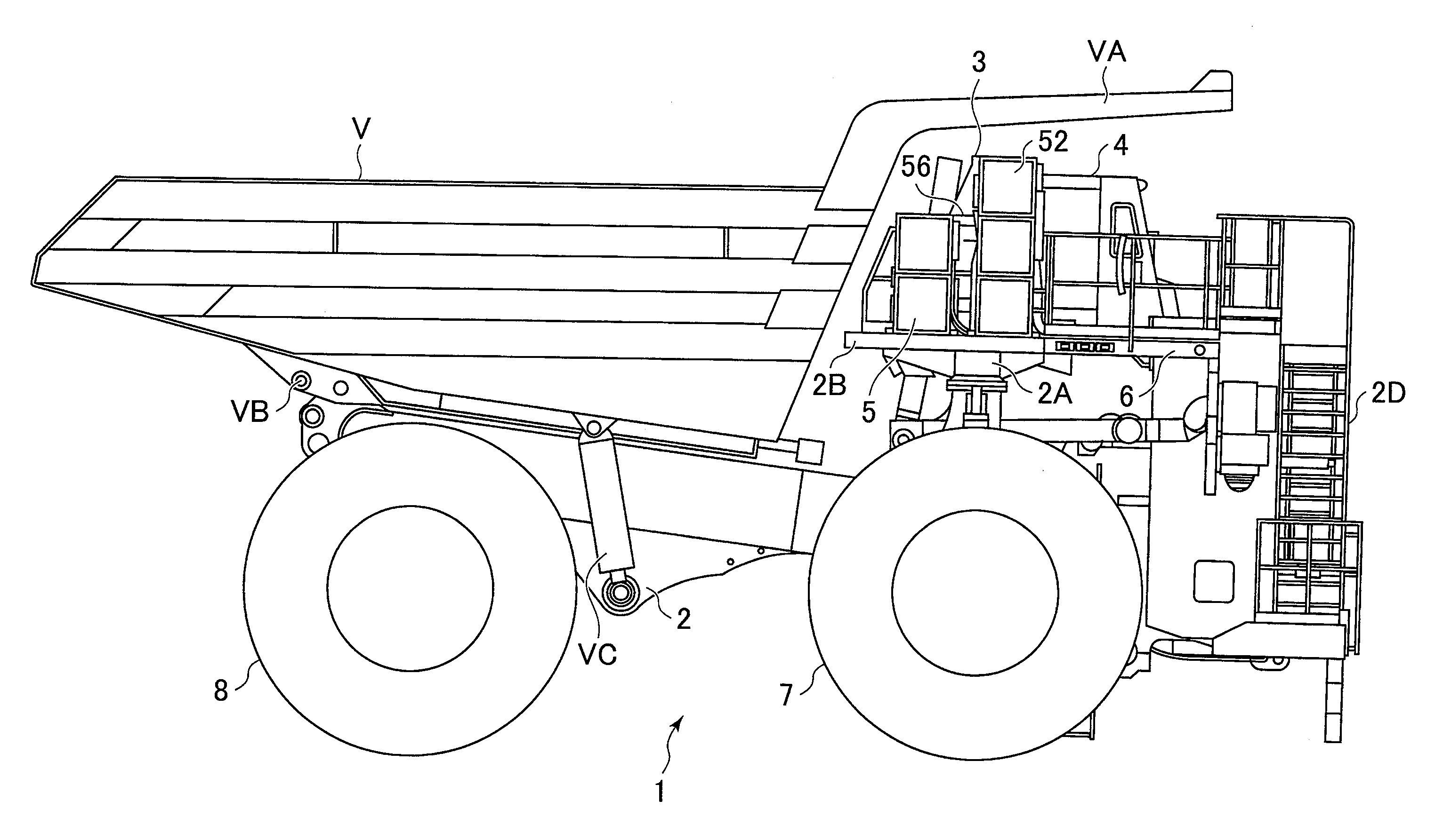
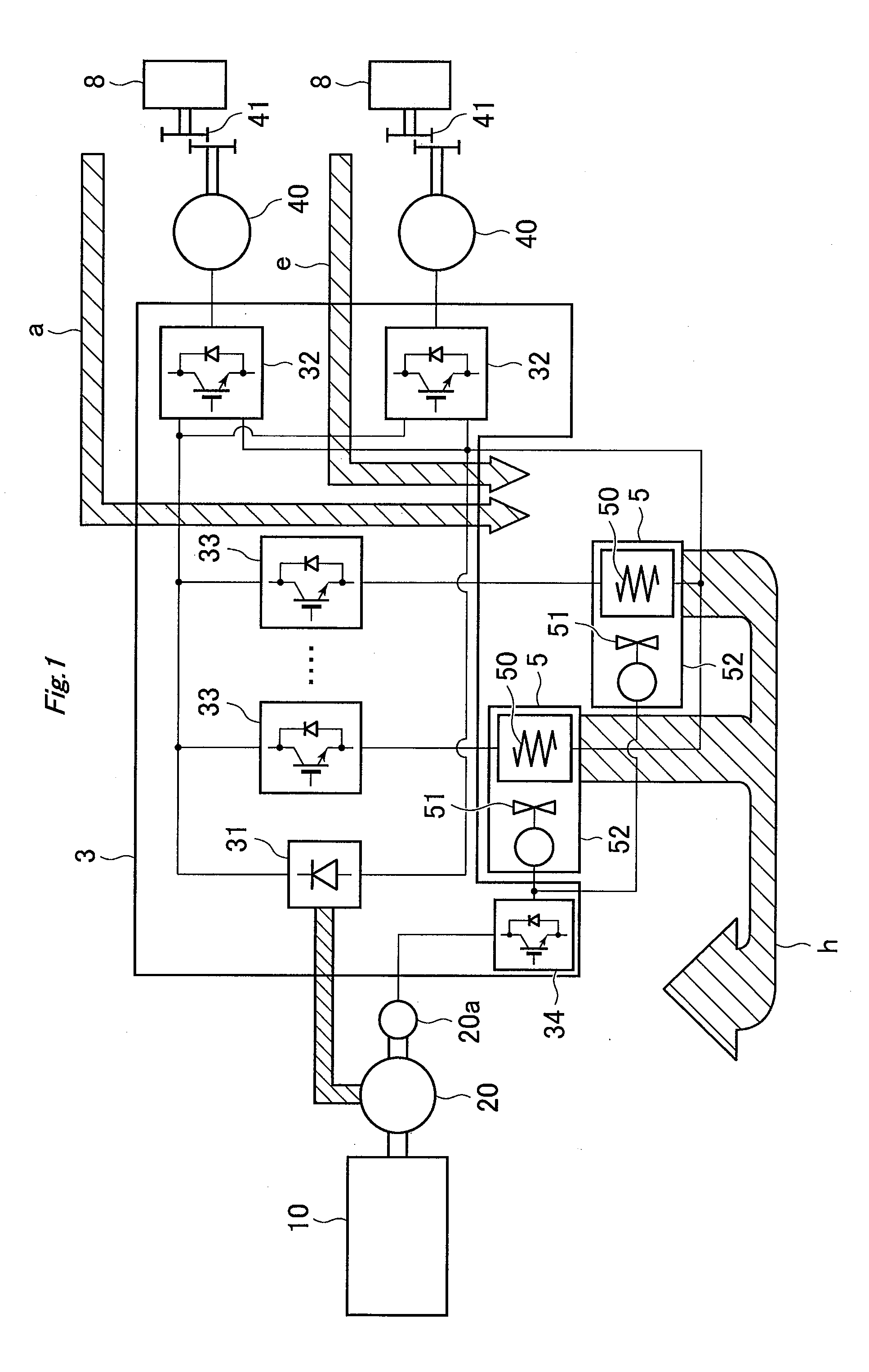
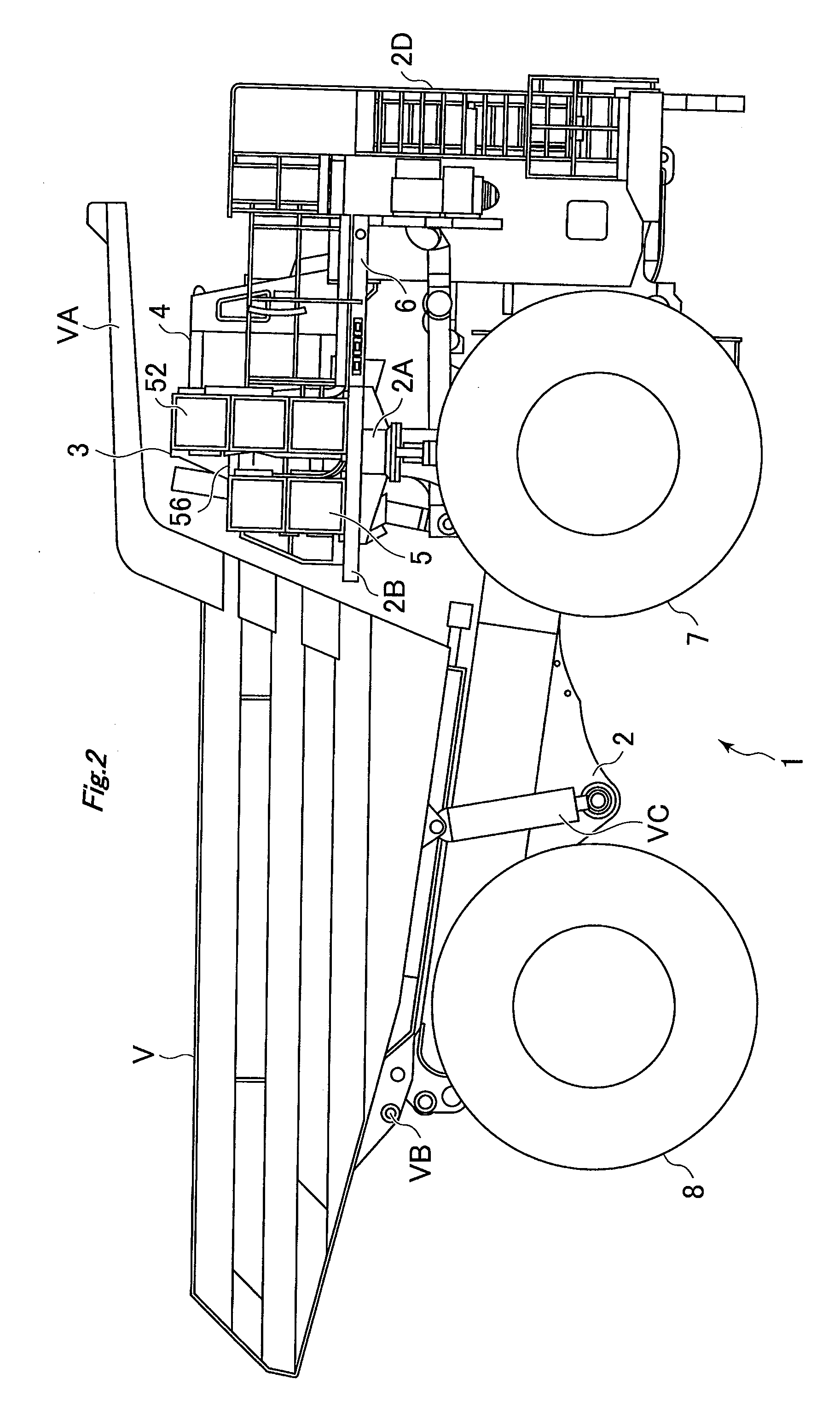
[0031]FIG. 1 is a conceptual diagram illustrating the structure of the drive unit of an electrically-driven dump truck 1 according to the invention. The drive unit comprises the following components: a diesel engine 10, or a prime mover (hereinafter referred to simply as “engine 10”); a main generator 20 connected to the engine 10 via a rotary shaft; an auxiliary generator 20a connected to the rotary shaft of the main generator 20; a control cabinet 3 that converts AC power from the main generator 20 into electric power at any desired frequency; wheel-drive electric motors 40 that obtain rotative power by receiving the electric power from the control cabinet 3; and resistor boxes 5 that each house a resistor 50 that consumes the regenerative electric power e that occurs during retarder braking operation.

[0032]The control cabinet 3 comprises the following components: a rectifier 31 that rectifies AC power from the main generator 20; inverters 32 that convert the rectified power by th...

second embodiment

[0063]Since the outlet ports 54 of the resistor boxes 5 of the second embodiment are arranged so as to face forward, the warm air that results from cooling the resistors 50 is never blown toward the vessel V but discharged forward. Thus, the warm air will not stay below the canopy VA, and the control cabinet 3 and the cab 4, both of which are located to the left of the resistor boxes 5, remain unaffected by the warm air.

[0064]Further, since the cooling fans 51 of the resistor boxes 5 of the second embodiment face the slope section of the vessel V, the propagation of the noise of the cooling fans 51 into the cab 4 can be suppressed by the control cabinet 3. As a result, the noise level inside the cab 4 can be reduced, which in turn improves the operating environment inside the cab 4.

[0065]Although the arrangement of the resistor boxes 5 according to the second embodiment is such that the outlet ports 54 of the resistor boxes 5 face forward, the resistor boxes 5 can instead be arrange...

third embodiment

[0067]In the invention, a support frame 60 which is made, for example, of steel and substantially turned square U-shaped in cross-section is attached to the bottom section of the deck 6 with a flat section of the support frame 60 parallel to the deck 6. An extra resistor box 5 is mounted on this flat section of the support frame 60 with a longitudinal direction of the extra resistor box 5 parallel to a width direction of the body frame 2. The floor surface of the deck 6 under which the support frame 60 is attached is provided with a removable cover. In mounting the extra resistor box 5 on the support frame 60, the removable cover of the deck 6 is first removed, and the extra resistor box 5 is then mounted on the flat section of the support frame 60. Thereafter, the removable cover is attached back to the deck 6 so as to cover the upper section of the extra resistor box 5.

[0068]In the thus-configured electrically-driven dump truck 1 of the third embodiment as well, sufficient space c...


PUM


Abstract

An electrically-driven dump truck 1 uses resistors to convert electric power generated during retarder braking operation into heat energy. A body frame 2 has front and rear wheels, a support base 2A, a cab 4 mounted on an upper left surface of the support base, and a control cabinet 3 mounted on an upper surface of the support base. A plurality of resistor boxes 5 are mounted on an upper base plate 2B and are arranged in a stacked manner such that the plurality of resistor boxes 5 are located to the right of the control cabinet 3 in order to secure right side visibility from the cab 4. Each resistor box has a casing with plural resistors connected in parallel, an inlet port and an outlet port. A fan for cooling the resistors is housed in the casing.

Description

BACKGROUND OF THE INVENTION[0001]1. Field of the Invention[0002]The present invention relates generally to electrically-driven dump trucks and specifically to an electrically-driven dump truck with increased side visibility.[0003]2. Description of the Related Art[0004]A dump truck refers generally to a truck with a mechanical apparatus that is used to unload all the loaded material from its dump box at a time by lifting the front of the dump box. There are two types of dump trucks: on-road and off-road dump trucks. The off-road dump trucks are specifically designed for use at large-scale construction sites or mines. Such off-road dump trucks have been increased in size for the purpose of improving labor efficiency. For instance, giant dump trucks are now widely used at strip mines around the world.[0005]For the purpose of improving the efficiency and maintainability of such giant dump trucks, their drive scheme is now shifting from a diesel-engine direct drive scheme to an electric ...

Claims


Application Information

Patent Timeline
Patent Type & Authority Applications(United States)
IPC IPC(8): B60K1/00B60R16/04B60L50/13
CPCB60K1/02B60K6/46B60K6/52B60L7/06B60L7/22Y02T10/7077B60L2260/28B60Y2200/14B60Y2200/142Y02T10/6217Y02T10/6265B60L11/123B60L50/61Y02T10/62Y02T10/70Y02T10/7072
Inventor FUSHIKI, MICHIOKOZAWA, HAJIMUYAGYUU, TAKASHIYASUDA, TOMOHIKOIMAIE, KAZUHIRO
Owner NIHON KENKI CO LTD
Why Eureka
Try Eureka