
Fastening Device and a Computer Case Having the Fastening Device

Inactive Publication Date: 2010-03-04
AOPEN
View PDF31 Cites 1 Cited by
  • Summary
  • Abstract
  • Description
  • Claims
  • Application Information

AI Technical Summary

Benefits of technology

[0010]Therefore, an object of the present invention is to provide a fastening device with a stable structure and that facilitates replacement.
[0011]Another object of the present invention is to provide a computer case including a fastening device with a stable structure and that facilitates replacement.
[0023]By extending each of the positioning parts of the positioning component from the outer face of the side wall of the positioning frame into the respective one of the two holes and the respective one of the two blind holes of the electronic device, and by virtue of the limiting part that limits the rod body of the positioning component from movement in a direction away from the sidewall of the positioning frame, the present invention is able to fasten the electronic device stably with a simple structure. Additionally, the positioning component has an advantage of ease of replacement.

Problems solved by technology

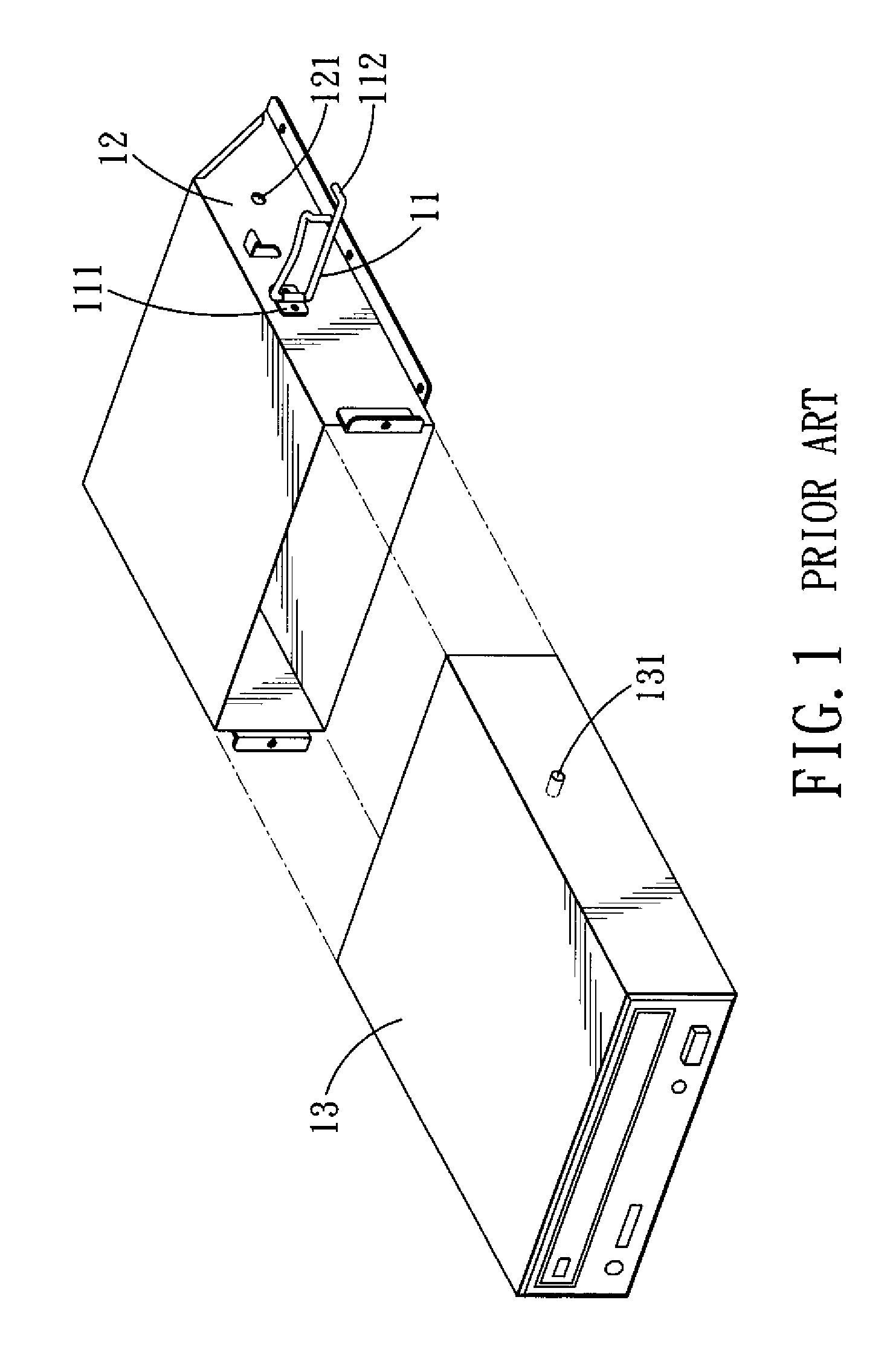
Thus, it takes a relatively long time to assemble and disassemble the data storage device, and an additional tool (a screwdriver, for example) is needed during assemble and disassemble.

Method used


Image

  • Fastening Device and a Computer Case Having the Fastening Device
  • Fastening Device and a Computer Case Having the Fastening Device
  • Fastening Device and a Computer Case Having the Fastening Device

Examples


Embodiment Construction

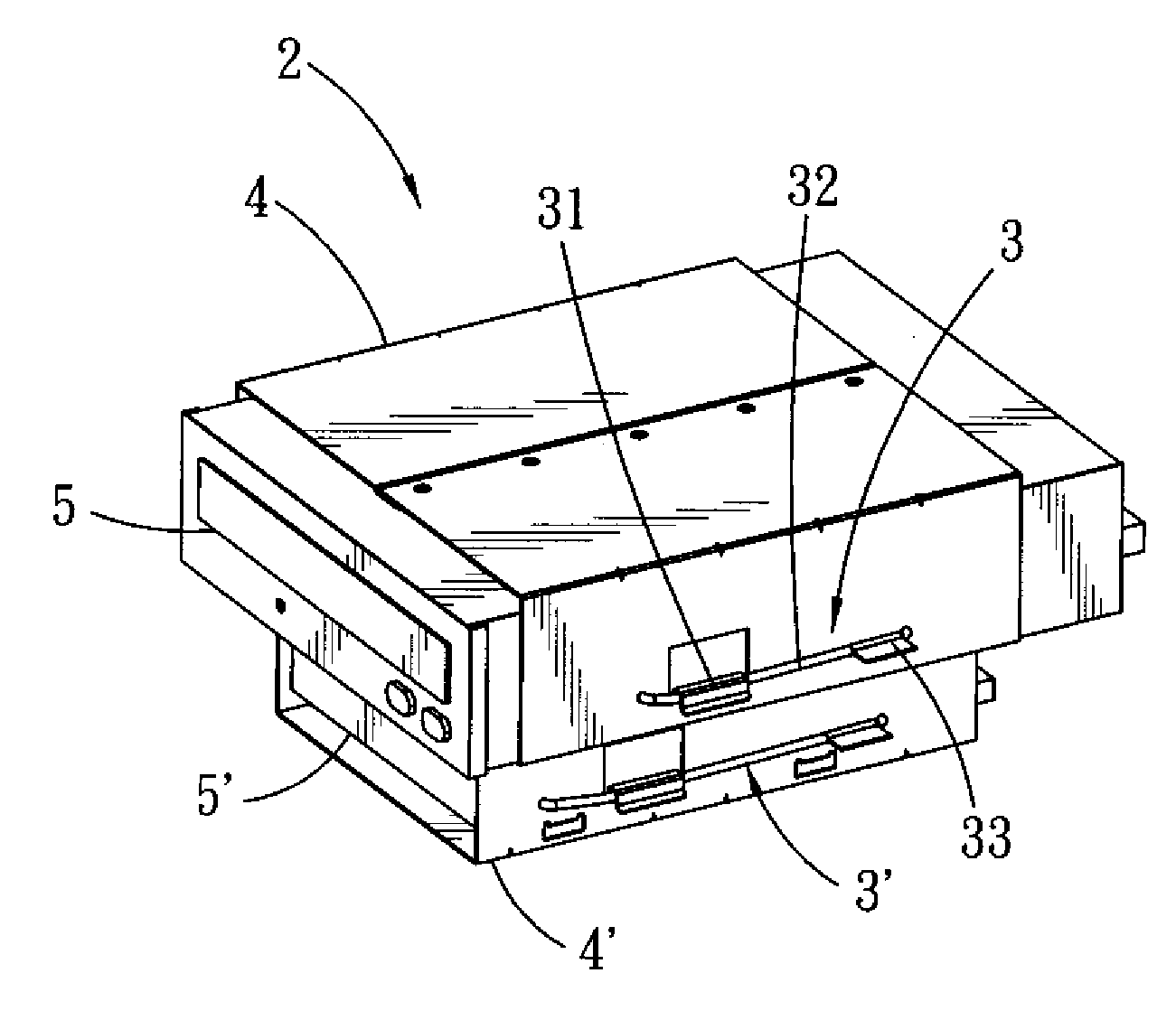
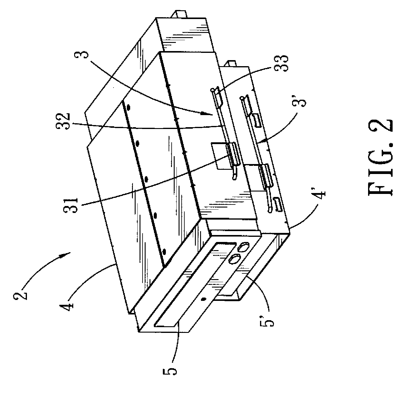
[0030]Referring to FIGS. 2 and 3, a preferred embodiment of a computer case 2 having fastening devices according to the present invention includes two positioning frames 4, 4′ connected to each other with one on top of the other. An electronic device 5 is disposed in the positioning frame 4, and an electronic device 5′ is disposed in the positioning frame 4′. The computer case 2 further includes a fastening device 3 provided on the positioning frame 4 for fastening of the electronic device 5, and a fastening device 3′ provided on the positioning frame 4′ for fastening of the electronic device 5′.

[0031]Since the assembling relationship among the fastening device 3′, the positioning frame 4′ and the electronic device 5′, and an assembling relationship among the fastening device 3, the positioning frame 4 and the electronic device 5 are the same, only the assembling relationship among the fastening device 3, the positioning frame 4 and the electronic device 5 will be described in the f...


PUM


Abstract

A fastening device is provided on a side wall of a positioning frame for fastening of an electronic device disposed in the positioning frame. The fastening device includes a limiting component and a positioning component. The limiting component includes a connecting part connected to an outer face of the side wall, and a limiting part extending from the connecting part and spaced apart from the side wall. The positioning component includes a rod body, and two positioning parts extending respectively from two ends of the rod body. Each of the positioning parts extends into a respective one of two holes in the side wall and a respective one of two blind holes in the electronic device. The rod body is limited from movement in a direction away from the side wall by the limiting part.

Description

CROSS-REFERENCE TO RELATED APPLICATION[0001]This application claims priority of Taiwanese Application No. 097215787, filed on Sep. 2, 2008.BACKGROUND OF THE INVENTION[0002]1. Field of the Invention[0003]The present invention relates to a fastening device, more particularly to a fastening device with a stable structure and that facilitates replacement.[0004]2. Description of the Related Art[0005]Generally, desktop personal computers have data storage devices, such as a hard drive, an optical disc drive, etc. When it is intended to assemble a data storage device to a computer case, it is typical to dispose the data storage device in a positioning frame in the computer case, followed by fastening the data storage device to the positioning frame using screws. Thus, it takes a relatively long time to assemble and disassemble the data storage device, and an additional tool (a screwdriver, for example) is needed during assemble and disassemble.[0006]Therefore, a screw-less fastener has bee...

Claims


Application Information

Patent Timeline
IPC IPC(8): H05K5/02H05K7/18
CPCG11B33/12
Inventor WANG, HSIN-HSIUNGCHANG, CHUN
Owner AOPEN
Learn More