Circuit Arrangement and Method for Operating a Discharge Lamp with Preheatable Electrodes

a discharge lamp and circuit arrangement technology, applied in the direction of electrical equipment, instruments, light sources, etc., can solve the problems of heavy load of the components involved, the risk of the power switch being destroyed,

Inactive Publication Date: 2010-03-04
OSRAM GMBH
View PDF3 Cites 0 Cited by
  • Summary
  • Abstract
  • Description
  • Claims
  • Application Information

AI Technical Summary

Benefits of technology

[0011]Provision is preferably furthermore made for the blocking apparatus to comprise an electronic switch, which has a control electrode, the control electrode firstly being connected to a deactivation signal, which is designed to deactivate the blocking apparatus in the switched-on state of the lamp generator, and an activation signal, which is designed to activate the blocking apparatus in the switched-off state of the lamp generator. In this case, it is preferred if the activation signal has been correlated with a voltage of the circuit arrangement which is sufficient for switching on the electronic switch without the presence of the deactivation signal, the deactivation signal having been correlated with a voltage which has, only in the switched-on state of the lamp generator, an amplitude which is sufficient for blocking the electronic switch despite the presence of the activation signal. This measure avoids complex gate logic since the activation signal and the deactivation signal can both be applied to the control electrode of the electronic switch, with the deactivation signal, if it is present in this case, prevailing over the activation signal.
[0012]In a preferred development, the lamp generator has a trapezoidal capacitor, the electronic switch being a bipolar transistor, the activation signal having been correlated with the input voltage, and the deactivation signal having been correlated with the voltage across the trapezoidal capacitor, in particular with the voltage rate of rise du / dt. This provides the advantage that the generation of the activation signal and of the deactivation signal can be performed virtually without any additional components, i.e. without any additional costs and without any additional population complexity.

Problems solved by technology

One solution which could consist in routing the startup circuit of the switching unit for power factor correction via at least one lamp filament is nevertheless an option since otherwise the so-called active “pull down” of the power switch driven by the switching unit for power factor correction, which power switch is generally a MOSFET, could not be ensured under all operating conditions and the risk of destruction of this power switch would arise.
This procedure is repeated although no lamp has been inserted, and this results in heavy loading of the components involved.

Method used


Image

  • Circuit Arrangement and Method for Operating a Discharge Lamp with Preheatable Electrodes
  • Circuit Arrangement and Method for Operating a Discharge Lamp with Preheatable Electrodes

Examples


Embodiment Construction

[0006]The object of the present invention is therefore to develop a generic circuit arrangement and / or a generic method in order to avoid intermittent operation of the switching unit for power factor correction with minimum complexity in terms of circuitry and to ensure reliable activation of the switching unit for power factor correction within desired periods of time.

[0007]This object is achieved by a circuit arrangement for operating a discharge lamp having the features of patent claim 1 and by a method for operating a discharge lamp having the features of patent claim 3.

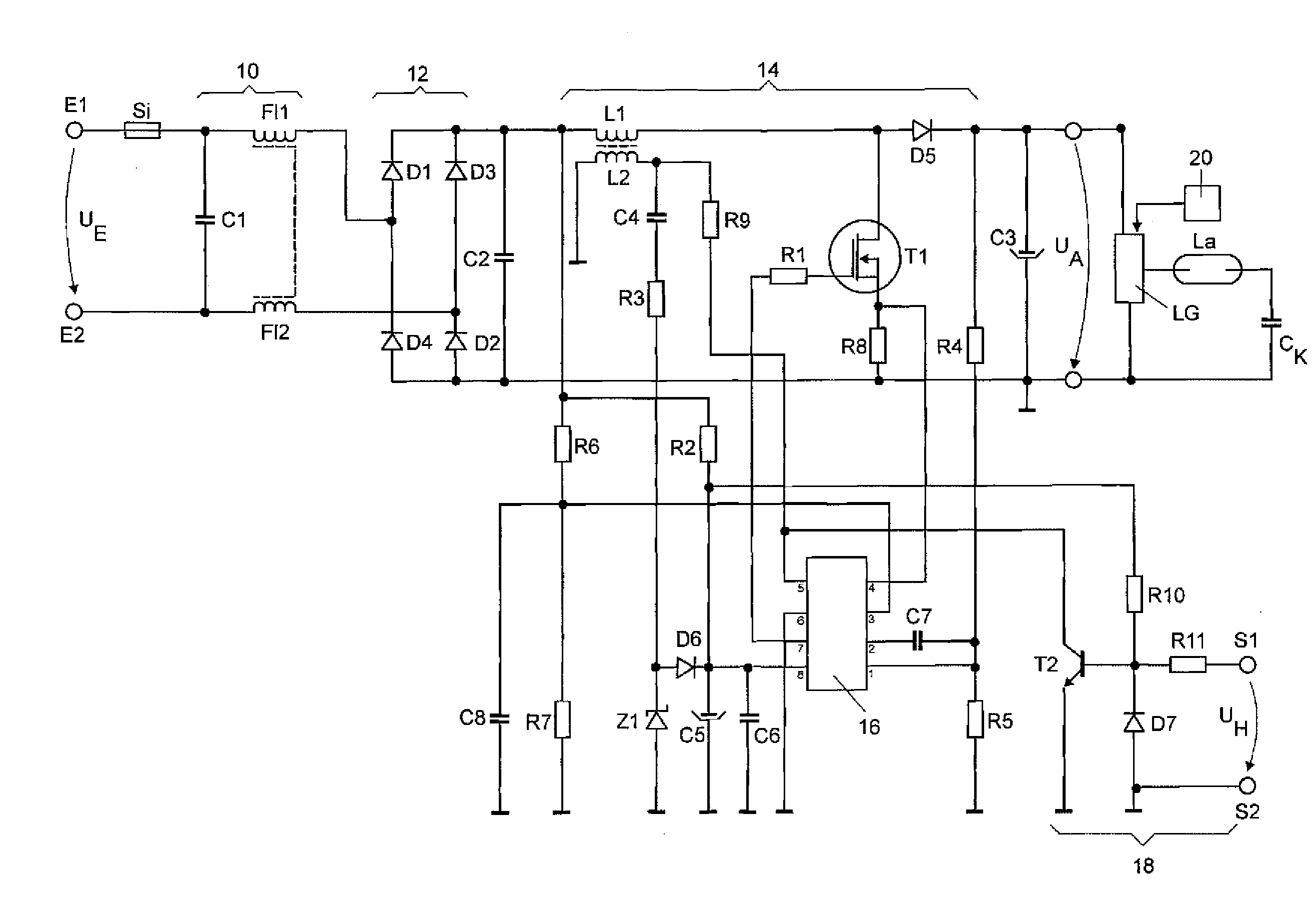
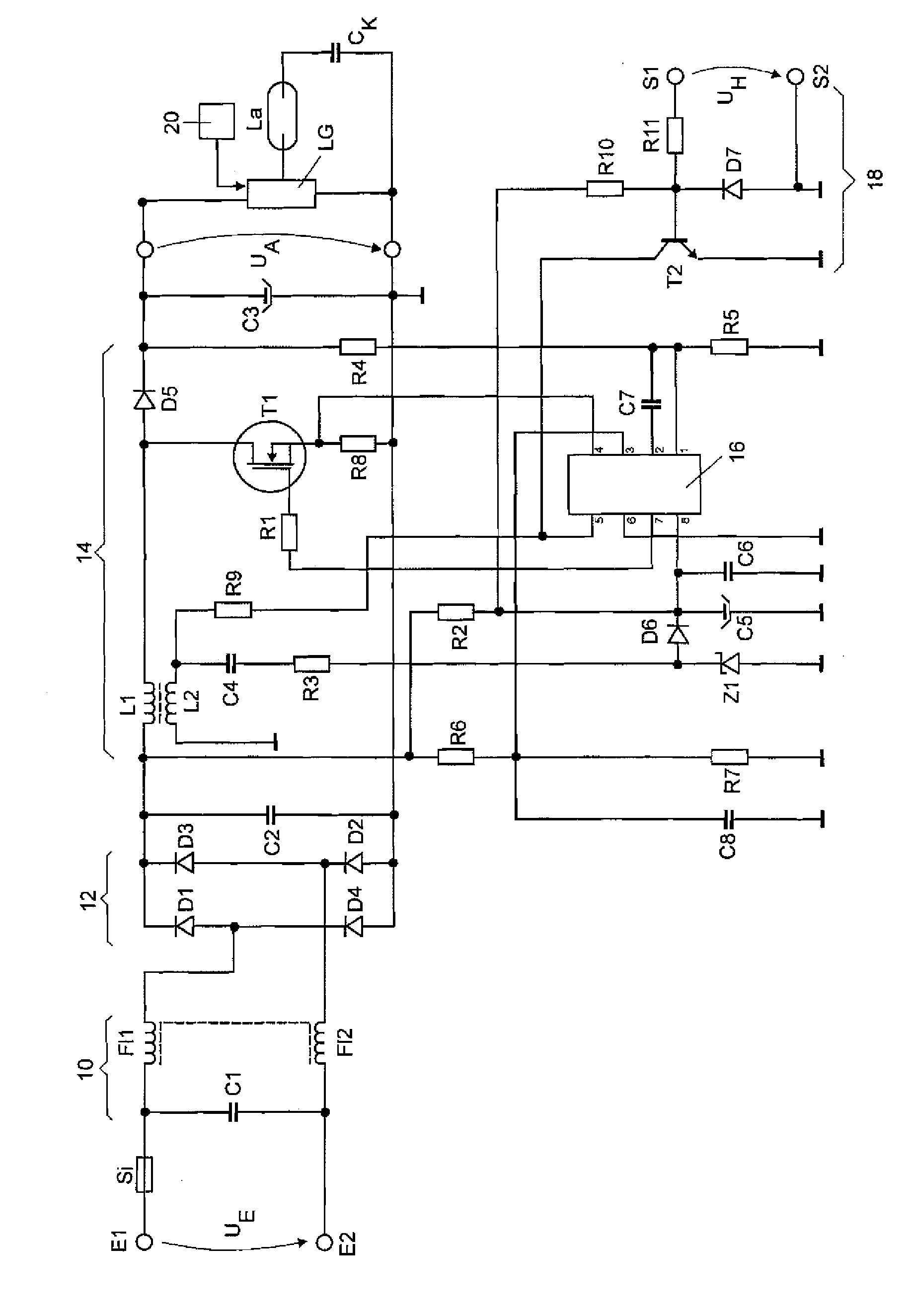
[0008]The present invention is based on the knowledge that the above object can be achieved if a blocking apparatus is provided which is coupled to the lamp generator in accordance with the master / slave principle, with the lamp generator representing the master and the blocking apparatus representing the slave. That is to say that as soon as the lamp generator is switched off as a result of the occurrence of a fa...


PUM


Abstract

A circuit arrangement for operating a discharge lamp (LA) with preheatable electrodes comprising: an input terminal for applying an input voltage (UE); an output terminal for providing an output voltage (UA) to a lamp generator (LG) for operating the discharge lamp (LA); a switching unit (14) for power factor correction which is coupled between the input terminal and the output terminal; a monitoring apparatus (20) which is adapted to switch off the lamp generator (LG) in the event of the presence of at least one switch-off criterion; an integrated circuit (16), which is adapted to drive the switching unit (14) for power factor correction, the integrated circuit (16) having a disable input; and a blocking apparatus (18), which is adapted to generate a blocking signal at its output when the lamp generator (LG) is switched off, the output of the blocking apparatus (18) being coupled to the disable input of the integrated circuit (16).

Description

TECHNICAL FIELD[0001]The present invention relates to a circuit arrangement for operating a discharge lamp with preheatable electrodes with an input terminal for applying an input voltage, an output terminal for providing an output voltage to a lamp generator for operating the discharge lamp, a switching unit for power factor correction which is coupled between the input terminal and the output terminal, a monitoring apparatus which is designed to switch off the lamp generator in the event of the presence of at least one switch-off criterion and an integrated circuit, which is designed to drive the switching unit for power factor correction, the integrated circuit having a disable input.PRIOR ART[0002]The present invention relates to the problem that a fault event of a circuit arrangement for operating a discharge lamp with preheatable electrodes generally occurs directly at the lamp generator, for example when the lamp is removed, in the case of a lamp which does not start or at Eo...

Claims


Application Information

Patent Timeline
Patent Type & Authority Applications(United States)
IPC IPC(8): H05B41/36
CPCH05B41/2855H05B41/295
Inventor RUDOLPH, BERND
Owner OSRAM GMBH
Why Eureka
Try Eureka