Apparatus having image shake correction function and method of controlling the same

a technology of optical apparatus and shake correction, which is applied in the field of optical apparatus having shake correction function, can solve the problems of image shake, degradation of captured images, and non-negligible image degradation

Inactive Publication Date: 2010-03-04
CANON KK
View PDF5 Cites 16 Cited by
  • Summary
  • Abstract
  • Description
  • Claims
  • Application Information

AI Technical Summary

Benefits of technology

[0012]The determining unit can determine the correction amount based on a result of assigning weights to the respective rotation radiuses at the plurality of the frequencies such that a rotation radius for which there is a small phase difference between the angular velocity and the velocity is assigned a weight that is larger than that assigned to a rotation radius for which there is a large phase difference.
[0013]The determining unit can determine the correction amount based on a result of assigning weights to the respective rotation radiuses at the plurality of the frequencies such that a rota

Problems solved by technology

Shake acting on a photographic apparatus, such as a camera, often causes image shake and hence degradation of a captured image.
However, in short-distance photography (large-magnification-ratio photographing condition), there is non-negligible image degradation due to shift shake acting on a camera orthogonally relative to the optical axis of the camera, which cannot be detected by using only an angular velocity sensor.
However, the output of the acceleration sensor is likely to be affected by a change in the environment such as disturbance noise and temperature es

Method used


Image

  • Apparatus having image shake correction function and method of controlling the same
  • Apparatus having image shake correction function and method of controlling the same
  • Apparatus having image shake correction function and method of controlling the same

Examples


first embodiment

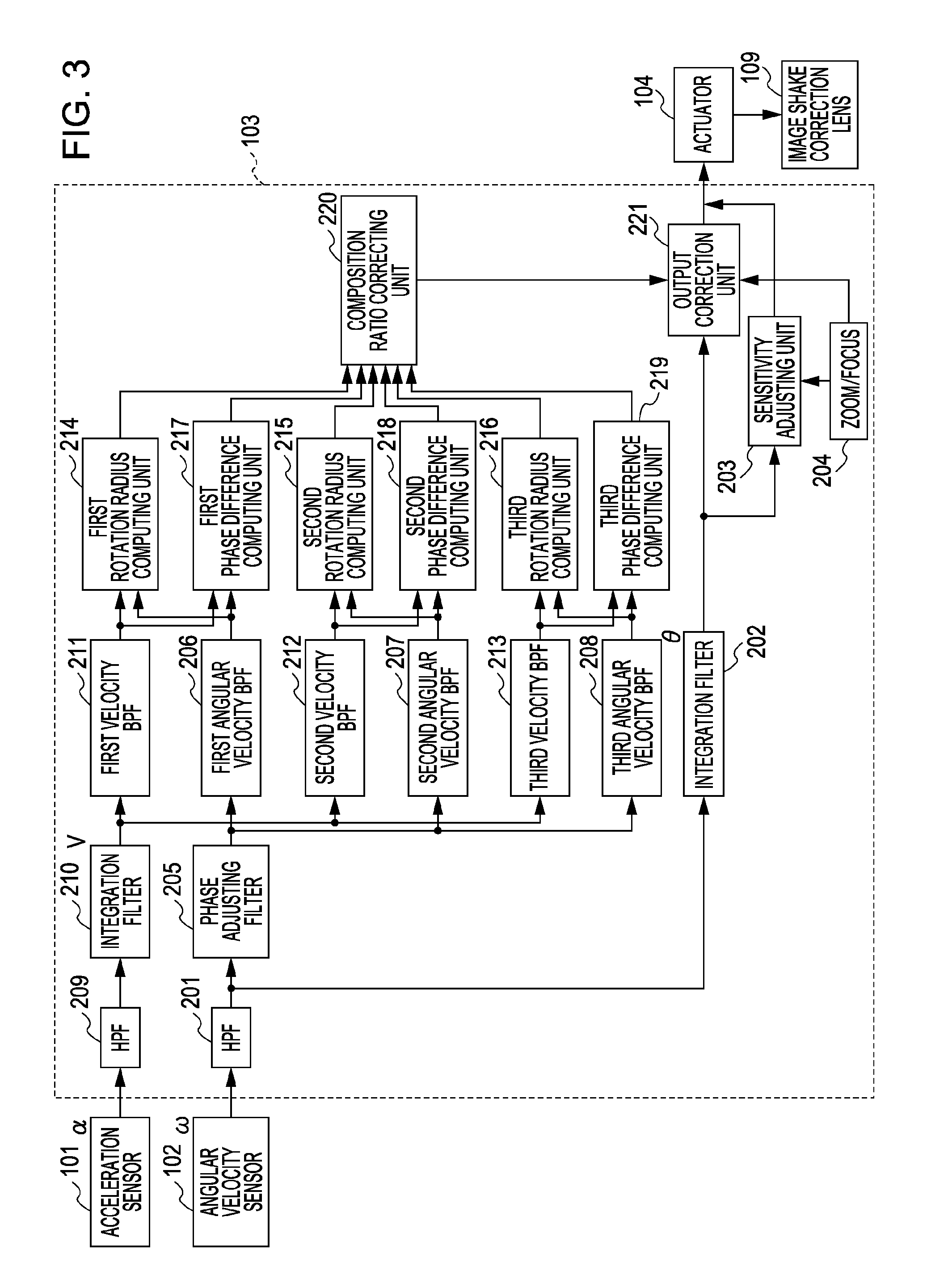
[0042]In a first embodiment, the reliability of each rotation radius is evaluated on the basis of a phase difference between an angular velocity, which is the output of the angular velocity sensor 102, and a velocity obtained from the output of the acceleration sensor 101. In accordance with the evaluation results, weighted rotation radiuses are combined to produce a composite rotation radius, on the basis of which, a correction amount is determined.

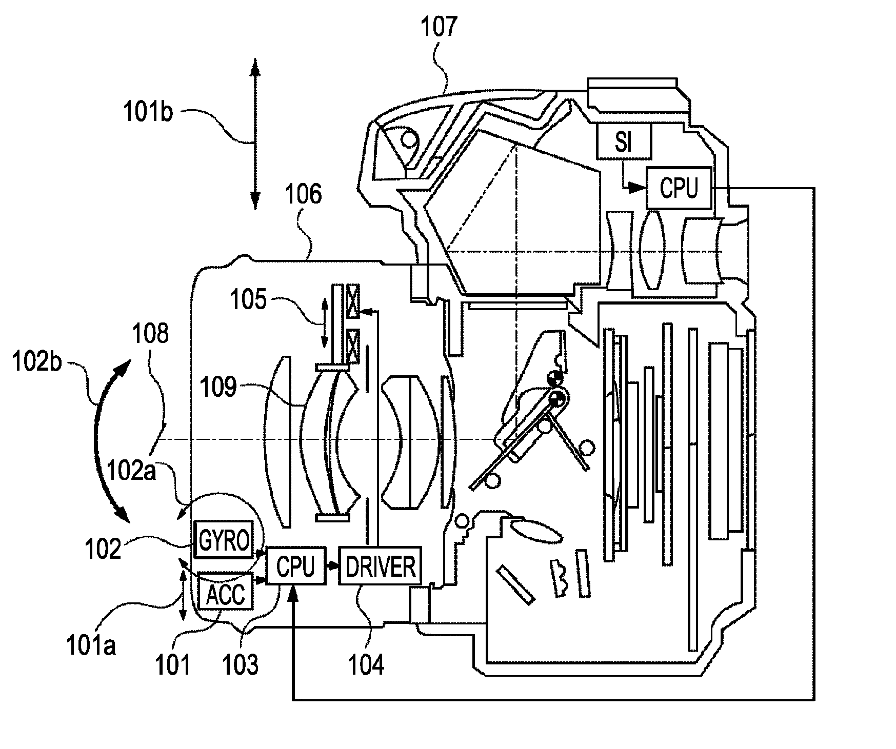
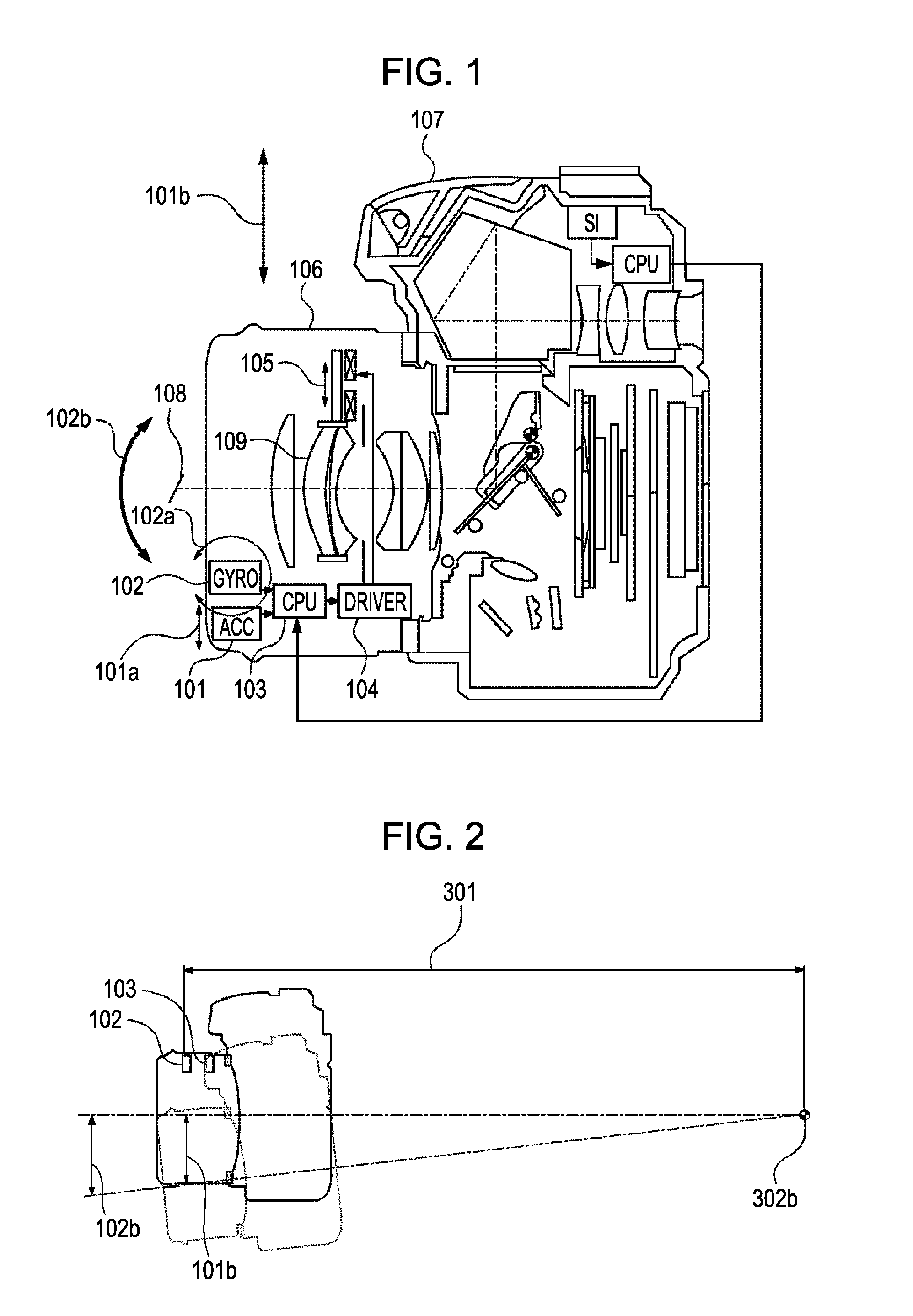
[0043]FIG. 3 shows a block diagram of an image stabilizer system that realizes the above-described determination of a correction amount and correction for shake. This block diagram shows a configuration that detects pitch-direction shake of a camera. Since a configuration for the yaw-direction is similar to this, only the configuration for the pitch direction will be described.

[0044]First, correction for angular shake, which is disclosed as a known technology, will be described. The output of the angular velocity sensor 102 is input to t...

second embodiment

[0097](1) The phase difference computing units 217 to 219 have been replaced with amplitude computing units 701 to 703, which compute the amplitudes of the angular velocity sensor 102. In other words, in the second embodiment, composition of a rotation radius is performed on the basis of the outputs of a first amplitude computing unit and a second amplitude computing unit for at least two frequencies (first and second frequencies) to determine a correction amount.

[0098](2) In the processing performed by the composition ratio correcting unit 220 in the first embodiment, a larger composition weight is assigned to a rotation radius for which there is a smaller phase difference; however, in the present embodiment, a larger composition weight is assigned to a rotation radius corresponding to an angular velocity having a larger amplitude.

[0099]First, the reason for using angular velocity amplitudes to adjust the rotation radius composition ratio will be described. A rotation radius is com...


PUM


Abstract

An apparatus and a method of controlling the apparatus are provided that can realize high-accuracy correction of image shake due to shift shake. Rotation radiuses at a plurality of frequencies among the frequency components of the shift shake are obtained. Correction amount is determined based on a result of assigning a respective weight to the rotation radius at each of the plurality of the frequencies based on information regarding at least one of an angular velocity and acceleration.

Description

BACKGROUND OF THE INVENTION[0001]1. Field of the Invention[0002]The present invention relates to an image stabilizing system. More particularly, the present invention relates to an optical apparatus having an image shake correction function, and a control method thereof.[0003]2. Description of the Related Art[0004]Shake acting on a photographic apparatus, such as a camera, often causes image shake and hence degradation of a captured image. Known technologies for reducing the influence of shake include a technology in which camera shake is detected using an angular velocity sensor, and by, for example, moving part of the lenses or shifting the position of a window used to cutout visible images from frames output from an image sensor, and image shake on the surface of the image sensor is reduced. Since angular shake that can be detected by using this technology using an angular velocity sensor has a significant adverse influence on a captured image under most photographing conditions,...

Claims


Application Information

Patent Timeline
IPC IPC(8): H04N5/228G03B17/00
CPCG03B5/00G03D17/00
Inventor TSUKAMOTO, SUGURU
Owner CANON KK
Why Eureka
Try Eureka