Stationary remote control transmitting device

a technology of transmitting device and remote control, which is applied in the direction of transmission system, television system, instruments, etc., can solve the problems of operator unease, inability to convey to the user the direction, and inability to convey the operation of input operations

Inactive Publication Date: 2010-03-04
SMK CORP
View PDF7 Cites 35 Cited by
  • Summary
  • Abstract
  • Description
  • Claims
  • Application Information

AI Technical Summary

Benefits of technology

[0031]Given the invention above, the displaying unit is disposed in the center of the operating unit for rotational operation, making it possible to use the display of the displaying unit to convey to the operator, without error, the rotational operation directions for the operating unit, which change depending on the control content.
[0032]Additionally, because the rotational operation directions for the controlled device are displayed on the displaying unit and the direction that is displayed on the di...

Problems solved by technology

Consequently, because the displaying unit is separated from the jog dial, it is not possible to provide guidance through the display, on the displaying unit, of the rotational direction of the jog dial for performing the desired control, and thus there is a problem in that it is not possible to convey to the user the direction to which the rotational operation should be made.
Additionally, when performing rotational operation control of a controlled device in accordance with the rotational operation of the jog dial, in some cases the rotational operation directions of the controlled device will be opposite from the rotational operation directions of the jog dial, depending on the relative positioning of the remote control device and the controlled device, causing the operator to mistake the rotational operation dir...

Method used


Image

  • Stationary remote control transmitting device
  • Stationary remote control transmitting device
  • Stationary remote control transmitting device

Examples


Embodiment Construction

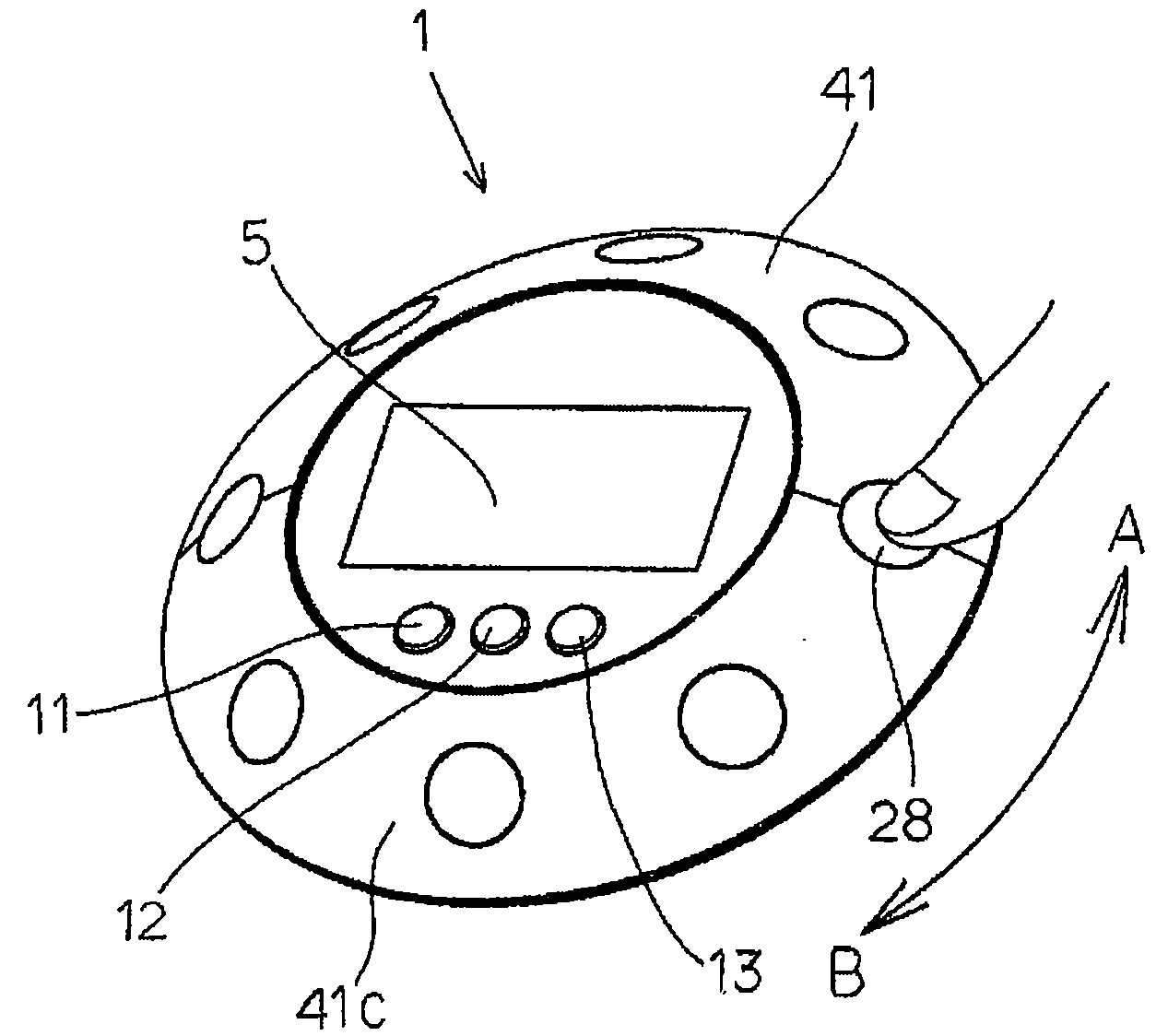
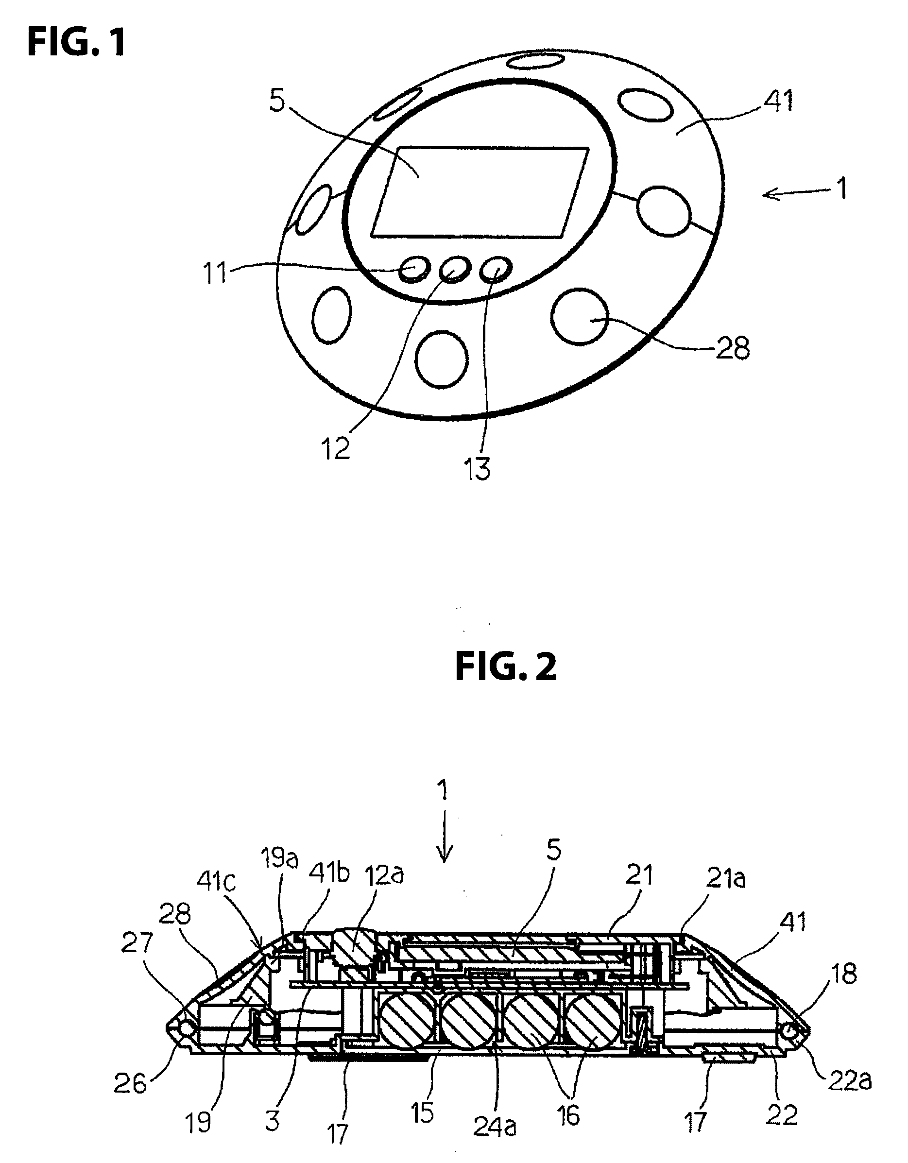
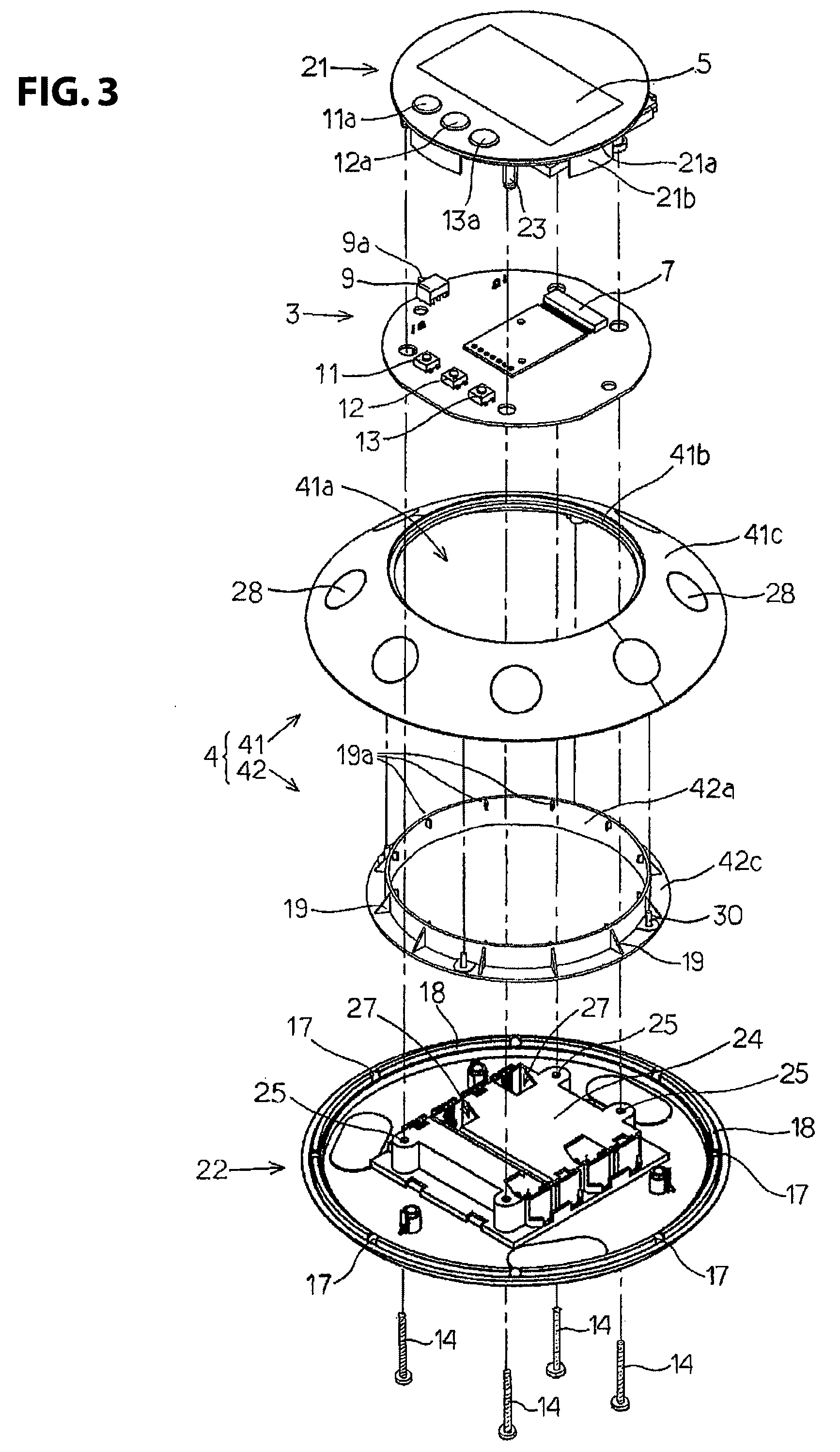
[0050]A stationary remote control transmitting device 1 as set forth in an embodiment according the present invention will be described below in reference to FIG. 1 through FIG. 9. FIG. 1 is an oblique view of a stationary remote control transmitting device 1; FIG. 2 is a lengthwise cross-sectional diagram of the same; FIG. 3 is an assembly oblique exploded view when seen from above the stationary remote control transmitting device 1; and FIG. 4 is an assembly oblique exploded view when viewed from below.

[0051]As illustrated in FIG. 3 and FIG. 4, the stationary remote control transmitting device 1 is provided with: an insulated case 2, structured from a small diameter disk portion 21 and a large diameter disk portion 22; a circular printed wiring board 2 that is attached interposed between the small diameter disk portion 21 and the large diameter disk portion 22; an annular operating unit 4 structured from a ring-shaped jog dial 41 and an operating ring 42; and three inputting switc...


PUM


Abstract

In a controlling mode wherein control content for rotational operation control of a controlled device has been selected through an inputting operation of an inputting switch, a displaying unit that is provided on a surface of a case that is displayed on the rotational center axis side of an operating unit displays the rotational operation directions for rotational operation control, to perform rotational operation control of a controlled device in a rotational operation direction displayed on the displaying unit by a rotational operation of an operating unit in a direction that matches the rotational operation direction that is displayed on the displaying unit.

Description

CROSS REFERENCE TO RELATED APPLICATION[0001]This application claims priority under 35 U.S.C. §119 to Japanese Patent Application No. 2008-224128 filed Sep. 1, 2008. The contents of that application, in their entirety, are incorporated herein by reference.FIELD OF TECHNOLOGY[0002]The present invention relates to a stationary remote control transmitting device for performing control by transmitting control data to a controlled device, and, more specifically, relates to a stationary remote control transmitting device provided with an operating unit for rotational operations.BACKGROUND OF THE INVENTION[0003]Conventionally, there are known remote control transmitting devices, as remote control transmitting devices for remotely controlling a video player device such as a DVD recorder, whereon a so-called “jog dial” annular dial key is attached to a case rotatably, and frame-by-frame or variable speed playback control of images recorded on the DVD recorder is performed in accordance with r...

Claims


Application Information

Patent Timeline
IPC IPC(8): H04N5/44H04N5/00H04Q9/00
CPCG08C17/02H01H2025/045H01H9/0235
Inventor OTSUKA, KENJI
Owner SMK CORP
Why Eureka
Try Eureka