Small projection lens and projection display device using the same

a projection display device and small technology, applied in the field of small projection lenses, can solve the problems of increased image size at a short distance, increased image size of a reduction-side lens, and difficulty in projecting images, and achieve the effects of wide angle of view, high projection performance, and high portability

Active Publication Date: 2010-03-04
FUJI PHOTO OPTICAL CO LTD
View PDF1 Cites 17 Cited by
  • Summary
  • Abstract
  • Description
  • Claims
  • Application Information

AI Technical Summary

Benefits of technology

[0011]The invention has been made in order to solve the above-mentioned problems, and an object of the invention is to provide a small projection lens that is applicable for a projection display device having high portability, and has a high projection performance and a wide angle of view such that an image size is increased during short-distance projection, and a projection display device using the same.

Problems solved by technology

However, the projection lens disclosed in JP-B-3508011 and JP-A-2005-84456 has a small angle of view of about 50 degrees, and it is difficult to project an image such that an image size is increased at a short distance.
However, JP-B-3508011 and JP-A-2005-84456 do not disclose any measures to prevent an increase in the size of a reduction-side lens and to actively reduce the size of the projection lens.
In addition, JP-B-3508011 and JP-A-2005-84456 do not disclose any measures to actively reduce the sizes of the reduction-side lens and a magnification-side lens with respect to an effective light beam.
However, JP-B-3508011 and JP-A-2005-84456 do not disclose this structure.

Method used


Image

  • Small projection lens and projection display device using the same
  • Small projection lens and projection display device using the same
  • Small projection lens and projection display device using the same

Examples


example 1

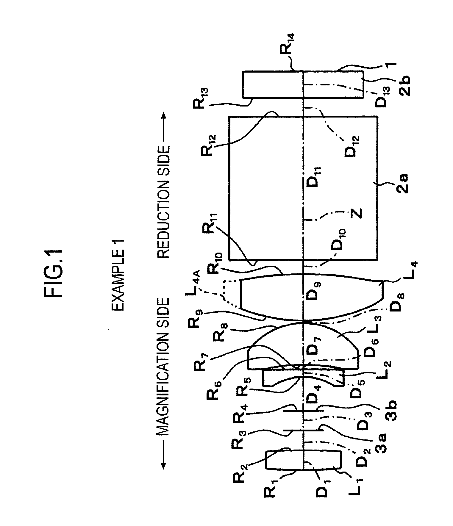
[0195]As shown in FIG. 1, a projection lens according to Example 1 includes a first lens L1, which is a biconvex lens, an aperture 3a, an aperture diaphragm (or an aperture) 3b, a second lens L2, which is a negative meniscus lens having a concave surface facing a magnification side, a third lens L3, which is a positive meniscus lens having a convex surface facing a reduction side, and a fourth lens L4, which is a biconvex lens having aspheric surfaces at both surfaces on the optical axis Z. The first to fourth lenses are arranged in this order from the magnification side.

[0196]The fourth lens L4 arranged closest to the reduction side is formed in a non-circular shape including an effective light beam transmission area to remove an unnecessary lens portion (a portion disposed at an upper part of FIG. 1) L4A (a so-called D-cut is performed), in order to prevent the outside diameter of a reduction-side lens from being excessively large.

[0197]The aspheric shapes of both surfaces of the ...

example 2

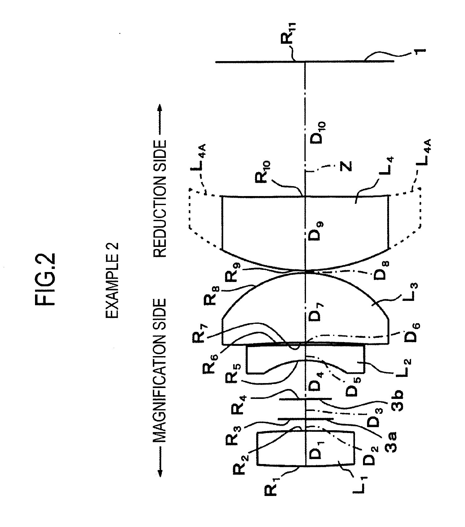
[0204]The structure of a projection lens according to Example 2 is shown in FIG. 2, and the structure of the projection lens according to Example 2 is substantially similar to that according to Example 1. However, the projection lens is configured so as to correspond to one light valve. Therefore, the glass block 2a for color composition shown in Example 1 is not provided between the fourth lens L4 and the image display surface 1 of the light valve. In addition, the illustration of the cover glass 2b of the light valve is also omitted.

[0205]The fourth lens L4 arranged closest to the reduction side is formed in a non-circular shape including an effective light beam transmission area to remove an unnecessary lens portion (a portion disposed in the vertical direction of FIG. 2) L4A (a so-called D-cut is performed), in order to prevent the diameter of a reduction-side lens from being excessively large.

[0206]The aspheric shapes of both surfaces of the fourth lens L4 are defined by the ab...

example 3

[0210]The structure of a projection lens according to Example 3 is shown in FIG. 3, and is substantially similar to that according to Example 1 except that the second lens L2 is biconcave lens.

[0211]The so-called D-cut according to Example 1 is not performed in Example 3.

[0212]The aspheric shapes of both surfaces of the fourth lens L4 are defined by the above-mentioned aspheric expression.

[0213]In Table 3, an upper part shows the curvature radius R of each lens surface in the projection lens according to Example 3, the on-axis surface spacing D between the lenses, the refractive index Nd of each lens with respect to the d-line, and the Abbe number νd thereof. In addition, in Table 3, a lower part shows an aspheric coefficient indicating each aspheric surface.

TABLE 3Surface NumberRDNdνdOBJ∞700.000 155.0561.4601.846723.8 2−35.3620.900 3 (mask)∞2.820 4 (mask)∞2.090 5−4.3320.6001.846723.8 668.7880.390 7−19.1332.9701.772549.6 8−5.2130.100 9*14.0913.2101.693553.210*−18.3181.71011∞12.0001....


PUM


Abstract

A small projection lens includes a first lens, which is a biconvex lens, an aperture, an aperture diaphragm (or an aperture), a second lens, which is a negative meniscus lens having a concave surface facing a magnification side, a third lens, which is a positive meniscus lens having a convex surface facing a reduction side, and a fourth lens, which is a biconvex lens having aspheric surfaces at both sides on an optical axis, arranged in this order from the magnification side.A minimum portion of the length of all lens elements of the small projection lens in a diametric direction vertical to the optical axis is equal to or less than 15 mm, and the small projection lens satisfies the following conditional expression:2.5<β / S<10.0 (where S indicates the maximum length of a magnification-side image (inch) and β indicates a magnifying power).

Description

CROSS-REFERENCE TO RELATED APPLICATIONS[0001]This application is based upon and claims the benefit of priority from the Japanese Patent Application No. 2008-223047 filed on Sep. 1, 2008 and Japanese Patent Application No. 2009-134591 filed on Jun. 4, 2009; the entire contents of which are incorporated herein by reference.BACKGROUND OF THE INVENTION[0002]1. Field of the Invention[0003]The present invention relates to a small projection lens that enlarges and projects, for example, display information from a light valve, such as a transmissive or reflective liquid crystal display device or a DMD (digital micro-mirror device), and more particularly, to a small projection lens applicable for a so-called handy-type projection display device having high portability, and a projection display device using the same.[0004]2. Description of the Related Art[0005]Projection display devices using light valves, such as a liquid crystal display device or a DMD display device, have come into widespr...

Claims


Application Information

Patent Timeline
Patent Type & Authority Applications(United States)
IPC IPC(8): G02B27/18G02B3/00G02B9/34G02B9/60G02B9/62G02B9/64
CPCG02B13/16G02B9/34
Inventor BABA, TOMOYUKIYAMAMOTO, CHIKARASADO, KENZO
Owner FUJI PHOTO OPTICAL CO LTD
Why Eureka
Try Eureka