Mosquito Repellent Lamp

a technology of mosquitoes and lamps, applied in the direction of lighting and heating apparatus, heating types, coupling device connections, etc., can solve the problems of patch volatilization and rapid consumption, poor odor dispelling effect, and add to the cost, so as to facilitate installation, improve the effect, and the effect of simple operation

Inactive Publication Date: 2010-03-04
SHEN JIANLI
View PDF8 Cites 11 Cited by
  • Summary
  • Abstract
  • Description
  • Claims
  • Application Information

AI Technical Summary

Benefits of technology

[0024]To make better use of the effect of the mosquito repellent patch, said cover is further connected with a ventilating device, which is provided with at least one ventilating hole that can be open and closed, and said ventilating holes are opposite to and can be connected to the air inlets on the base plate of said sleeve chuck. When the pull cylinder and sleeve chuck of said mosquito repellent device is not pulled, the ventilating device may quickly dispel the medical odor of the mosquito repellent patch to the ambience, thus form an airflow channel between the air inlets and the ventilating hole.
[0025]Said ventilating device may simply adopt the following structure which: comprising a bottom plate with said ventilating hole and a rotary plate rotatably connected on said bottom plate, said rotary plate is provided with grid holes capable of being aligned to said ventilating holes, when said rotary plate is turned so as to allows said grid holes to be aligned with corresponding ventilating hole, said ventilating holes are open; when said rotary plate is turned as so to makes said grid holes to be staggered with corresponding ventilating holes, said ventilating holes are closed. If the rotary plate is rotated, said grid holes and said ventilating holes can be aligned, thus to open said ventilating holes, the ventilating holes can be closed when the rotary plate is turned so as to align the grid holes on the rotary plate with the ventilating holes, the operation is very simple and convenient.
[0026]Said bottom plate is fixedly connected to said fan, moreover, said switchboard is fixed on said bottom plate, said switchboard is provided with said fan switch to turn and stop said fan, a slot hole is provided on the base plate of said sleeve chuck for allowing said fan switch to be led out. Thus said fan is directly fixed on said bottom plate, which can facilitate the installation, moreover, the air inlets on the base plate of the sleeve chuck may directly adhere to the fan tightly, thus the wind can be directly blown into the air inlets when the fan is turning, which achieved better effect.
[0027]When the bottom rim of said pull cylinder pushes against said fan switch, said fan is shut off and stopped due to the function of said switchboard; when the bottom rim of said pull cylinder is detached from said fan switch, said fan switch is raised and said fan is connected and start turning due to the function of said switchboard. Said pull cylinder and said sleeve chuck can slide axially relative to each other, while said fan switch turns on and off the fan through the bottom rim of said pull cylinder, the operation is simple and the structure is compact.
[0028]Compared with existing technologies, this invention has the following advantages: this invention provides air inlets and air outlets on the mosquito repellent device and an fan corresponding to air inlets, the airflow from the turning of the fan dispels the medical effect of the mosquito repellent patch inside the mosquito repellent device out of the air outlets, which achieved better mosquito repellent effect. In actual use, the mosquito repellent patch gradually dispels the medical effect under the afterheat of the luminous tube, since the inlets and outlets form a airflow channel, when the fan at air inlets is turned on, the airflow is blown into air inlets and brings the medical odor from the air outlets to the ambience, which broadens the range of medical effect, accelerates the spread of the medical effect of the mosquito repellent patch. Moreover, this invention utilizes the medical effect of the mosquito repellent patch instead of electric mesh for killing mosquitoes, which is safer and can prevent electric shock.
[0029]Furthermore, besides mosquito repellent patches, aromatics or deodorizers may also be placed in the mosquito repellent device to achieve the purpose of air purification or perfuming of the mosquito repellent device. This invention can also achieve the opening and closing of air outlets with the structure in which the cover, sleeve chuck and pull cylinder are mutually cooperated, the structure is reasonable and the operation is convenient and quick.

Problems solved by technology

However, both patents above adopt afterheat of the bulb to heat the mosquito repellent or perfuming patches so as to dispel the medical effect, which provides low heating energy for the patches, therefore the medical odor dispelling effect is poor, moreover, due to long-term contact with the air, the patches are subject to volatilization and quick consumption.
Compared with the traditional method to install mosquito repellent patches on incandescent lamps, this patent kills mosquitoes by mosquito repellent luminous tubes with the principle of spectra, however, the effect of this patent is only available within certain effective distance and is impacted by lighting, moreover, once the florescent powder layer is damaged or peeled off, it is required to replace the whole tube, which adds to the cost.
Furthermore, this lamp can only kill mosquitoes and has no effects of sterilization, deodorization and air purification.
Besides, there are also some mosquito repellent lamps at present utilizing suction force and hi-tension mesh, however, this kind of mosquito repellent lamps have the risk of electric shock and are not suitable to be used at home.

Method used


Image

  • Mosquito Repellent Lamp
  • Mosquito Repellent Lamp
  • Mosquito Repellent Lamp

Examples


Embodiment Construction

[0040]Detailed description of this utility model will now be described with reference to the drawings.

[0041]Please refer to FIG. 1˜FIG. 9 for the embodiment:

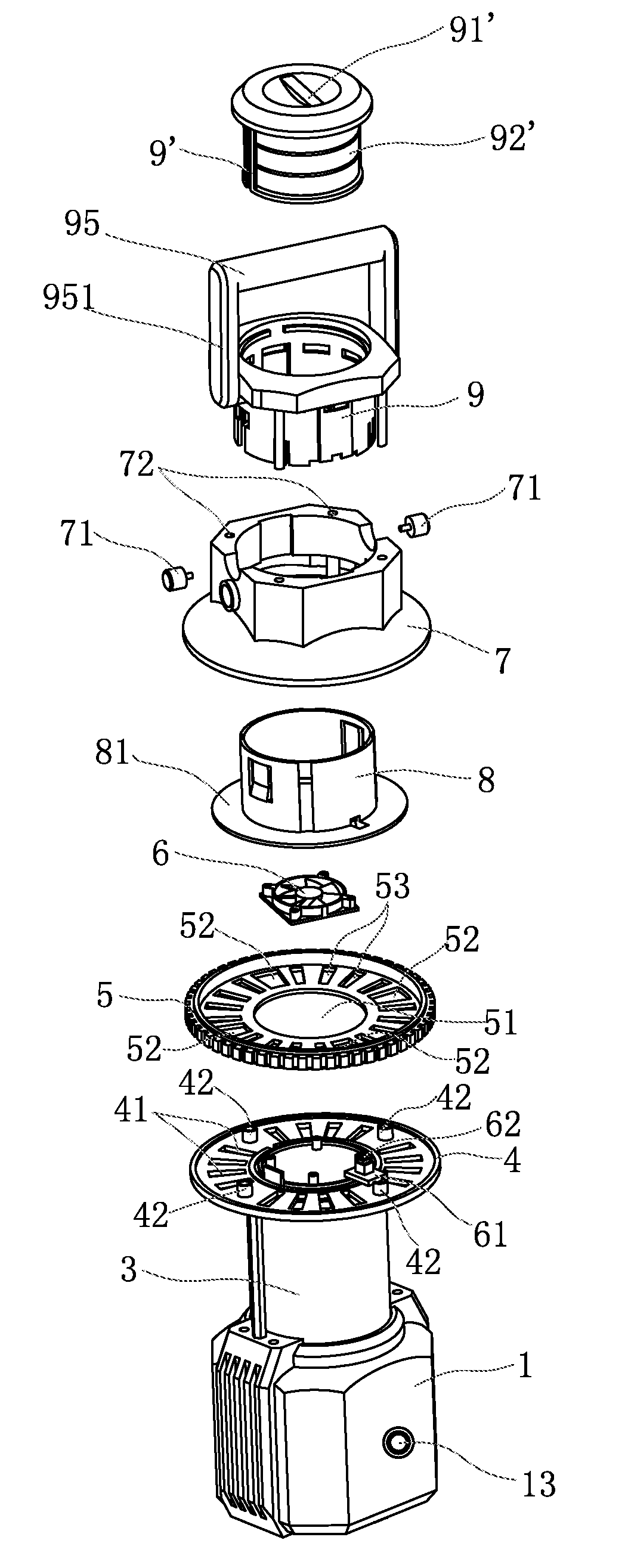
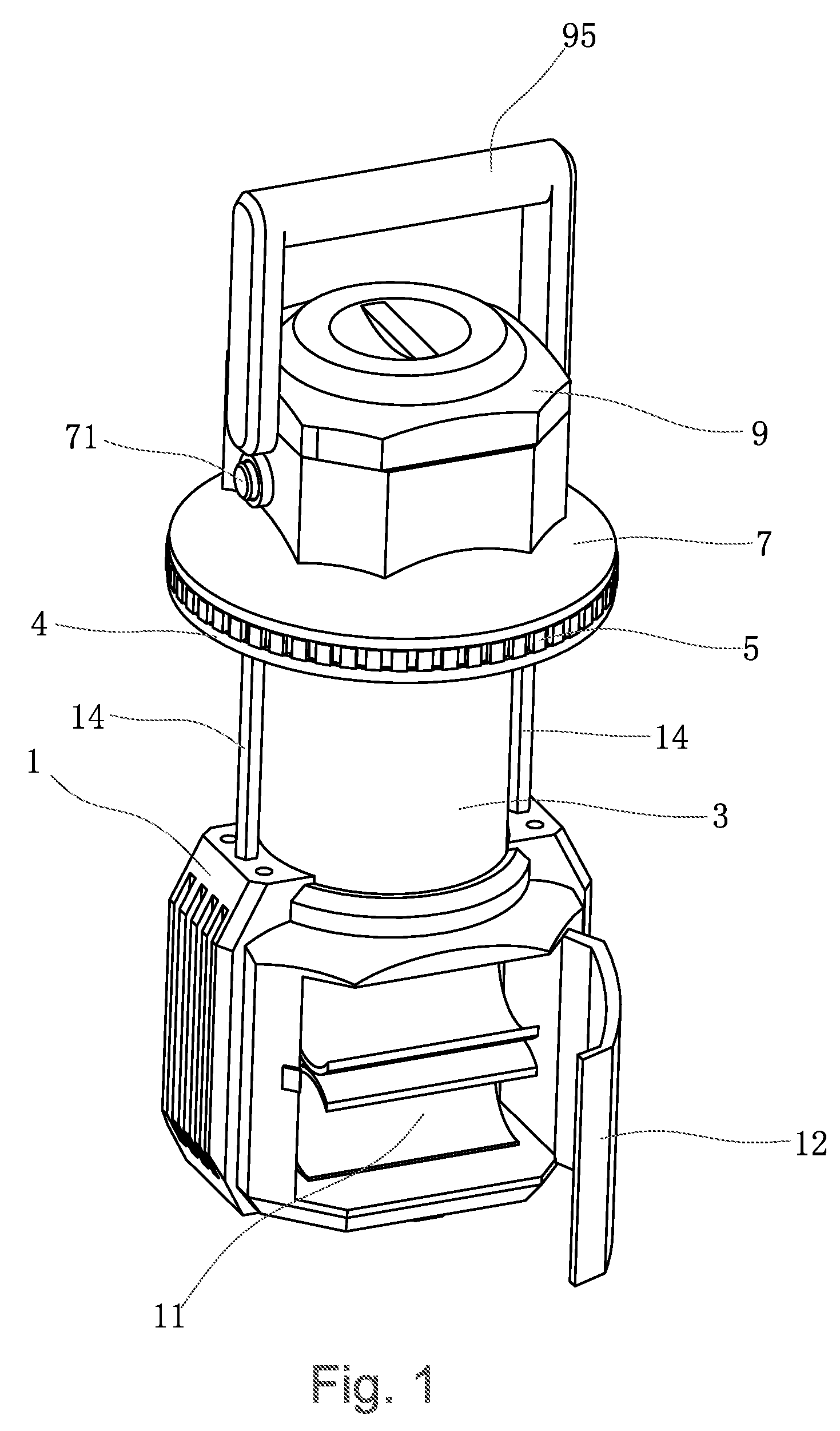
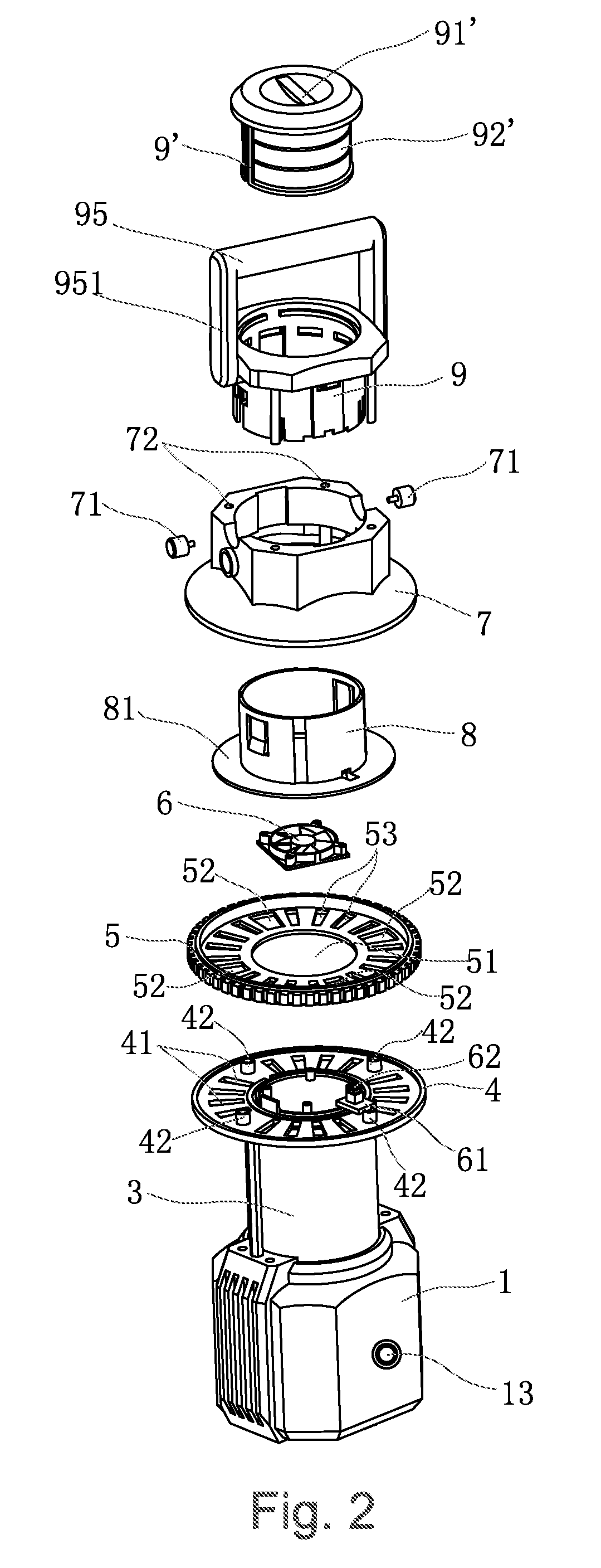
[0042]The mosquito repellent lamp as shown by this embodiment comprises the lamp holder 1, the LED luminous tube 2 and the lamp shade 3, where, the LED luminous tube 2 is mounted in said transparent lamp shade 3, which is fixed on said lamp holder 1, a cavity 11 for containing batteries is provided inside said lamp holder 1, said cavity 11 is further provided with a swinging door 12 that can be opened and closed, a power switch 13 is provided on the external surface of said lamp holder 1 connected electrically with batteries inside said cavity 11 to connect and disconnect the power of the luminous tube 2. In this embodiment, dry batteries or rechargeable batteries are accepted as power supply of the luminous tube, which is safer and can more effectively prevent electric shock.

[0043]A round bottom plate 4 is fixed on the top of t...


PUM


Abstract

A mosquito repellent lamp, comprising a lamp holder, which is provided with a lamp shade with luminous tube; a power switch for turning on and off the power; a mosquito repellent device mounted above said lamp shade; featured by that: said mosquito repellent device is provided with a cavity for contain mosquito repellent patch, which is provided with air inlets and outlets, which are interconnected, and a fan corresponding to the air inlets, said fan and said luminous tube are powered through a switchboard, which is connected with a fan switch for turning and stopping said fan. Compared with existing technologies, this patent provides the air inlets and air outlets on the mosquito repellent device and achieves better mosquito repellant effect by dispelling the effect of the mosquito repellent patch insides said mosquito repellent device from the air outlets by the airflow generated by said fan. Besides mosquito repellent patches, aromatics or deodorizers may also be placed in the mosquito repellent device to achieve the purpose of air purification or perfuming.

Description

CROSS REFERENCE TO THE RELATED PATENT APPLICATION[0001]The present application claims the priority of the Chinese patent application No. 200810120723.X filed on Sep. 2, 2008, which application is incorporated herein by reference.FIELD OF THE INVENTION[0002]This invention relates to a kind of mosquito repellent lamp, which has the effect of mosquito repelling, sterilization, deodorization and air purification while providing lighting.BACKGROUND OF THE INVENTION[0003]Considering mosquito sting in summer, people have thought of adding mosquito repellent device to lighting instruments, for instance, Chinese utility model patent number CN87203596 “Mosquito Repellent Device for Lighting Instruments”, Chinese utility model patent number CN85202716 “Double-duty Bulb for Lighting and mosquito repelling”, both adopt location or additional device on bulb for mosquito repellent chemicals, when the bulb is turned on, the afterheat of the bulb can be used for heat the mosquito repellent patch and...

Claims


Application Information

Patent Timeline
Patent Type & Authority Applications(United States)
IPC IPC(8): F21V33/00
CPCA01M29/12
Inventor SHEN, JIANLI
Owner SHEN JIANLI
Why Eureka
Try Eureka