Thermal sound generating device

a generation device and sound technology, applied in the direction of transducer details, instruments, electrical transducers, etc., can solve the problems of significantly reducing the generation efficiency of acoustic waves, hardly being able to completely eliminate a frequency component which is different from that of input signals, and output of input signals. , to achieve the effect of preventing the generation of joule hea

Inactive Publication Date: 2010-03-04
PIONEER CORP
View PDF5 Cites 78 Cited by
  • Summary
  • Abstract
  • Description
  • Claims
  • Application Information

AI Technical Summary

Benefits of technology

[0004]In this technology, however, it is hardly possible to completely eliminate a frequency component which is different from that of input signal (i.e. a strain component). The strain component can be reduced by increasing the direct current signal, superimposed on the alternating current signal, but this significantly reduces the generation efficiency of the acoustic waves.

Problems solved by technology

This causes such a technical problem that the acoustic wave signal which is different from the input signal is outputted.
In this technology, however, it is hardly possible to completely eliminate a frequency component which is different from that of input signal (i.e. a strain component).
The strain component can be reduced by increasing the direct current signal, superimposed on the alternating current signal, but this significantly reduces the generation efficiency of the acoustic waves.
In this construction, the resistance of the heating-element thin film increases with respect to the electric current because the electric current flows in a direction orthogonal to the film thickness direction of the heating-element thin film (in other words, horizontally to the thickness direction or planarly), resulting in a technical problem of an increase in the generation of the Joule heat.
The increased Joule heat regardless of the Peltiert element used as the heating element causes the aforementioned various problems.
Moreover, because of a small contact point between the heat-element thin film and a signal terminal, it is hardly possible to obtain a large temperature change by a thermoelectric effect.

Method used


Image

  • Thermal sound generating device
  • Thermal sound generating device
  • Thermal sound generating device

Examples


examples

[0067]Hereinafter, examples of the present invention will be explained with reference to the drawings.

(1) Basic Structure

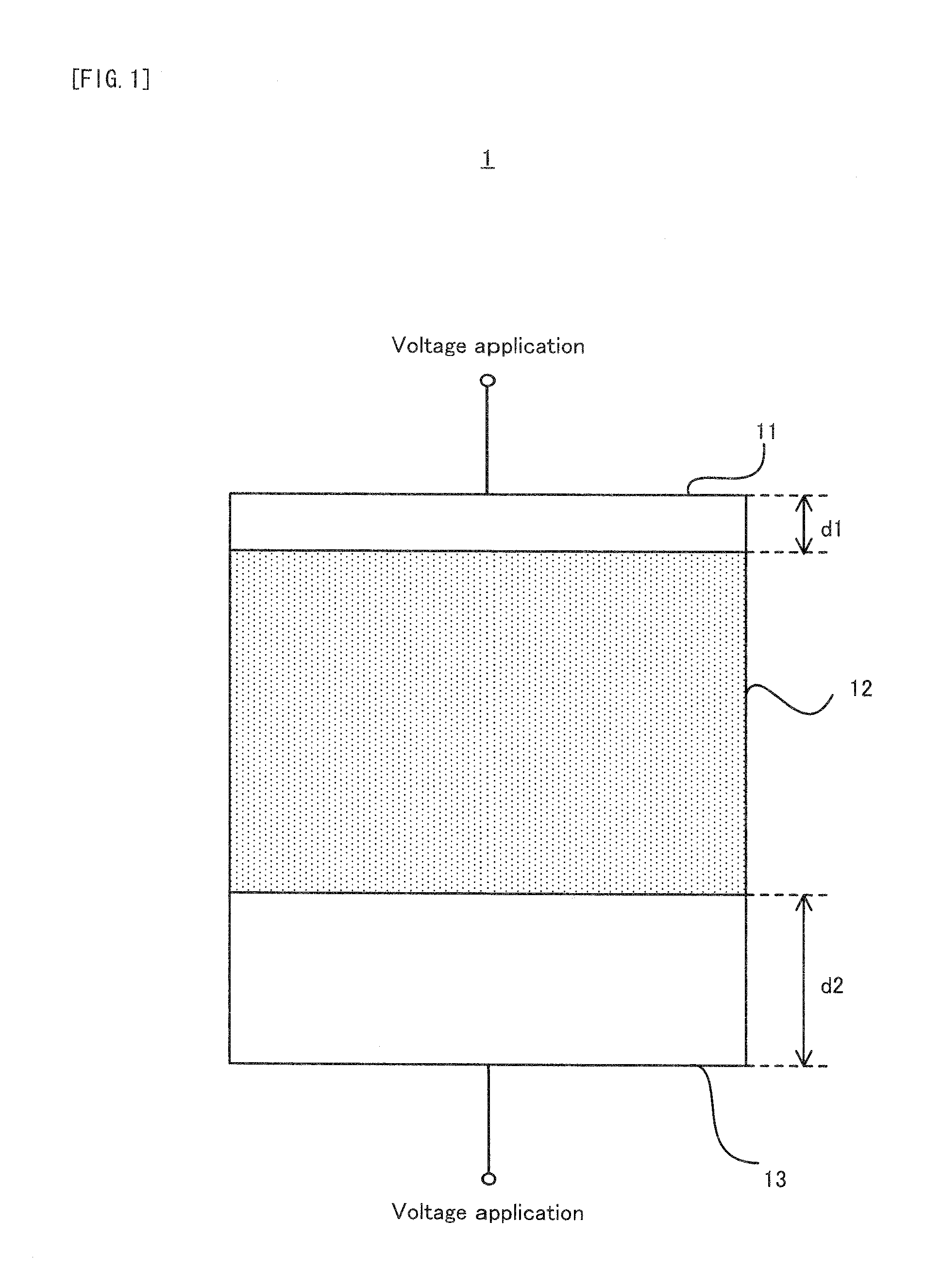
[0068]Firstly, with reference to FIG. 1, an explanation will be given on an example of the thermoacoustic generating apparatus of the present invention. FIG. 1 is a cross sectional view conceptually showing a first basic structure of a thermoacoustic generating apparatus 1 in an example.

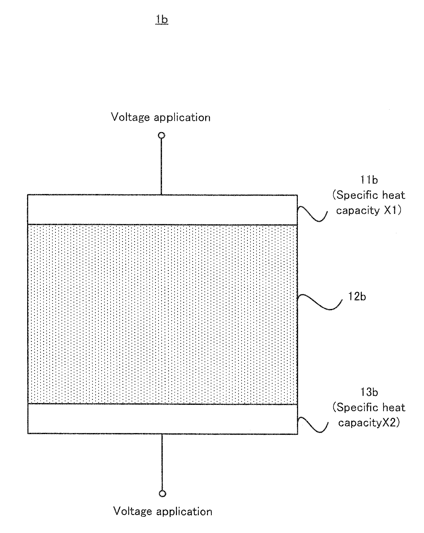
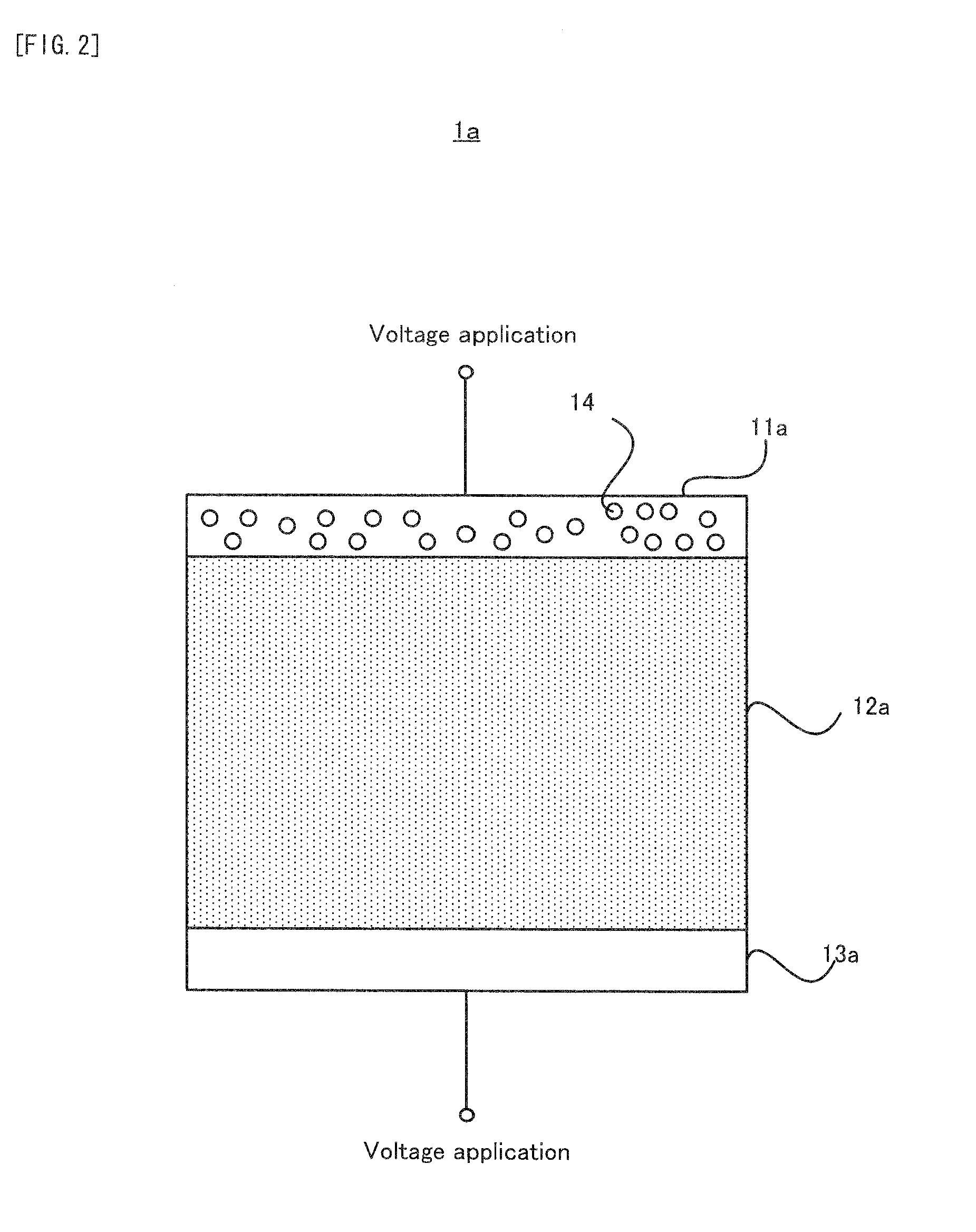
[0069]As shown in FIG. 1, the thermoacoustic generating apparatus 1 in the example is provided with an upper electrode 11, which constitutes one specific example of the “first electrode layer” of the present invention; a thermoelement 12, which constitutes one specific example of the “thermoelement layer” of the present invention; and a lower electrode 13, which constitutes one specific example of the “second electrode layer” of the present invention.

[0070]The upper electrode 11 is, for example, an electrode made of metal or the like with a film thickness of d1. More specifically, ...

first modified example

(2) First Modified Example

[0095]Next, with reference to FIG. 6 and FIG. 7, an explanation will be given on a first modified example of the thermoacoustic generating apparatus in the example. FIG. 6 is a perspective view conceptually showing a first basic structure of a thermoacoustic generating apparatus in the first modified example. FIG. 7 is a perspective view conceptually showing a second structure of the thermoacoustic generating apparatus in the first modified example.

[0096]As shown in FIG. 5, a thermoacoustic generating apparatus 100 in the first modified example is provided with a plurality of thermoacoustic generating units 10. Each of the plurality of thermoacoustic generating units 10 has substantially the same structure as those of the thermoacoustic generating apparatuses 1 shown in FIG. 1 to FIG. 4 and is provided with the upper electrode 11, the thermoelement 12, and the lower electrode 13.

[0097]In the thermoacoustic generating apparatus 100 in the first modified exam...

second modified example

(3) Second Modified Example

[0107]Next, with reference to FIG. 8 and FIG. 9, an explanation will be given on a second modified example of the thermoacoustic generating apparatus in the example. FIG. 8 is a perspective view conceptually showing a first basic structure of a thermoacoustic generating apparatus in the second modified example. FIG. 9 is a perspective view conceptually showing a second structure of the thermoacoustic generating apparatus in the second modified example.

[0108]As shown in FIG. 8, a thermoacoustic generating apparatus 102 in the second modified example is provided with the plurality of thermoacoustic generating units 10, as in the thermoacoustic generating apparatus 100 in the first modified example.

[0109]In the thermoacoustic generating apparatus 102 in the second modified example, only the p-type thermoelements 12-1 are used as the thermoelements 12. The plurality of p-type thermoacoustic generating units 10 are connected electrically in series to match the ...


PUM


Abstract

A thermoacoustic generating apparatus (1) is for generating acoustic waves by temperature modulation of solids, and is provided with: a thermoelement layer (12); a first electrode layer (11), laminated on one surface of the thermoelement layer; and a second electrode layer (13), laminated on the other surface of the thermoelement layer.

Description

TECHNICAL FIELD[0001]The present invention relates to, for example, a thermoacoustic generating apparatus for generating acoustic waves by temperature modulation of solids.BACKGROUND ART[0002]As the thermoacoustic generating apparatus, for example, patent documents 1 and 2 disclose such construction that voltage application is repeated on a resistance heating element and that Joule heat is used to temperature-modulate a thermal layer.Patent document 1: Japanese Patent Application Laid Open No. Hei 3-140100Patent document 2: Japanese Patent Application Laid Open No. Hei 11-300274Patent document 3: Japanese Patent Application Laid Open No. 2005-150797DISCLOSURE OF INVENTIONSubject to be Solved by the Invention[0003]In such construction that the Joule heat is used for the temperature modulation, an acoustic wave signal outputted as a result of the temperature modulation is on the order of the square of an input signal inputted to control the temperature modulation. This causes such a t...

Claims


Application Information

Patent Timeline
Patent Type & Authority Applications(United States)
IPC IPC(8): H04R1/00
CPCG10K15/04H04R23/002H01L35/32H10N10/17
Inventor MIYACHI, MAMORU
Owner PIONEER CORP
Why Eureka
Try Eureka