Developing roller and method of producing the roller, process cartridge, and electrophotographic image-forming apparatus

Active Publication Date: 2010-03-04
CANON KK
View PDF12 Cites 5 Cited by
  • Summary
  • Abstract
  • Description
  • Claims
  • Application Information

AI Technical Summary

Benefits of technology

[0018]According to a further aspect of the present invention, there is provided a developing roller capable of solving the above problems (1) and (2) at high levels. In addition, according to the present inventi

Problems solved by technology

When the surface of the developing roller has poor toughness, the surface of the developing roller is shaved upon long-term use of the developing roller, with the result that an i

Method used


Image

  • Developing roller and method of producing the roller, process cartridge, and electrophotographic image-forming apparatus
  • Developing roller and method of producing the roller, process cartridge, and electrophotographic image-forming apparatus
  • Developing roller and method of producing the roller, process cartridge, and electrophotographic image-forming apparatus

Examples


Example

Example 1

Preparation of Conductive Mandrel 2

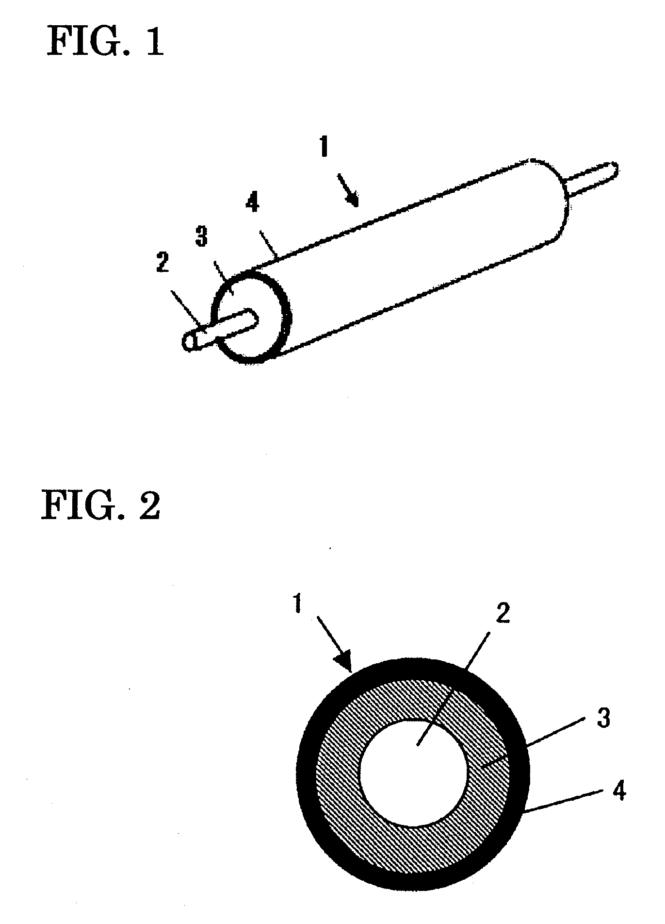
[0111]The conductive mandrel 2 was prepared by: applying a primer (trade name: DY35-051; manufactured by Dow Corning Toray Silicone Co., Ltd.) to a core metal having a diameter of 6 mm made of SUS304; and baking the applied primer at a temperature of 150° C. for 30 minutes.

[0112]3>

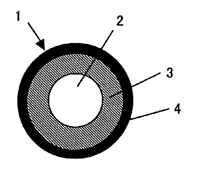
[0113]Next, the conductive mandrel 2 was placed in a die, and a liquid, conductive, silicone rubber (product manufactured by Dow Corning Toray Silicone Co., Ltd. and having an ASKER-C hardness of 40 degrees and a volume resistivity of 1×10⁵ Ω·cm) was injected into a cavity formed in the die. Subsequently, the die was heated, and the silicone rubber was vulcanized at 150° C. for 15 minutes. The resultant was removed from the die, and was then heated at 200° C. for 2 hours so that a curing reaction might be completed. Thus, the resin layer 3 having a diameter of 12 mm was provided on the outer periphery of the conductive mandrel 2.

[0114]4>

[0115]The following materi...

Example

Examples 2 to 32

[0117]Developing rollers were each prepared in the same manner as in Example 1 except that the formulation of the paint for forming a surface layer in Example 1 was changed as shown in Tables 2 and 3 below.

Example

Example 33

[0118]A developing roller was prepared in the same manner as in Example 1 except that the formulation of the paint for forming a surface layer in Example 1 was changed as shown below. The following materials were mixed and stirred with a stirring motor. The mixture was dissolved in MEK so that the total solid content might be 30 mass %, and then the contents were mixed. After that, the resultant was subjected to uniform dispersion with a sand mill, whereby the paint 1 for forming a surface layer was obtained.

Diol Compound A:56 parts by mass (as a solid)Diol Compound Z: 6 parts by mass (as a solid)Isocyanate Compound P:38 parts by mass (as a solid)Carbon black (trade name: MA100;25 parts by massmanufactured by MitsubishiChemical Corporation):Resin particles (trade name:30 parts by massART PEARL C600 transparent;manufactured by NegamiChemical Industrial Co., Ltd.):


PUM

PropertyMeasurementUnit
Percent by massaaaaaaaaaa

Abstract

The present invention intends to provide a method of producing a developing roller capable of providing high-quality electrophotographic images under a variety of environments. The method of producing a developing roller according to the present invention is a method of producing a developing roller having a mandrel, a resin layer on the outer periphery of the mandrel, and a surface layer on the outer periphery of the resin layer, the method including the step of curing a mixture containing a carbon black, a specific diol, and a specific isocyanate compound to form the surface layer.

Description

CROSS-REFERENCE TO RELATED APPLICATIONS[0001]This application is a continuation of International Application No. PCT / JP2009 / 059476, filed May 18, 2009, which claims the benefit of Japanese Patent Application No. 2008-143175, filed May 30, 2008.BACKGROUND OF THE INVENTION[0002]1. Field of the Invention[0003]The present invention relates to a developing roller for use in an electrophotographic image-forming apparatus adopting an electrophotographic mode such as a copying machine, a printer, or the receiving apparatus of a facsimile, and a method of producing the roller.[0004]In addition, the present invention relates to a process cartridge and an electrophotographic image-forming apparatus each of which uses the developing roller.[0005]2. Description of the Related Art[0006]A contact developing method has been known as a method of developing an image in an electrophotographic apparatus. In the contact developing method, an electrostatic latent image formed on a photosensitive drum is ...

Claims


Application Information

Patent Timeline
IPC IPC(8): G03G15/08B23P25/00
CPCG03G15/0818Y10T29/49885Y10T29/49563
Inventor NAKAMURA, MINORUTAKAYAMA, YOSHIYUKINAGAOKA, KAZUAKIYAMADA, MASAKI
Owner CANON KK
Why Eureka
Try Eureka