Filtration system for gas turbines

a technology of filtration system and gas turbine, which is applied in the direction of filtration separation, combustion air/fuel air treatment, separation process, etc., can solve the problems of corrosives entering the gas turbine, corroding the gas turbine elements, operating failures and financial losses

a technology of filtration system and gas turbine, which is applied in the direction of filtration separation, combustion air/fuel air treatment, separation process, etc., can solve the problems of corrosives entering the gas turbine, corroding the gas turbine elements, operating failures and financial losses

US20100054919A1Inactive Publication Date: 2010-03-04BHA ALTAIR

Image

  • Filtration system for gas turbines
  • Filtration system for gas turbines
  • Filtration system for gas turbines

Examples


Embodiment Construction

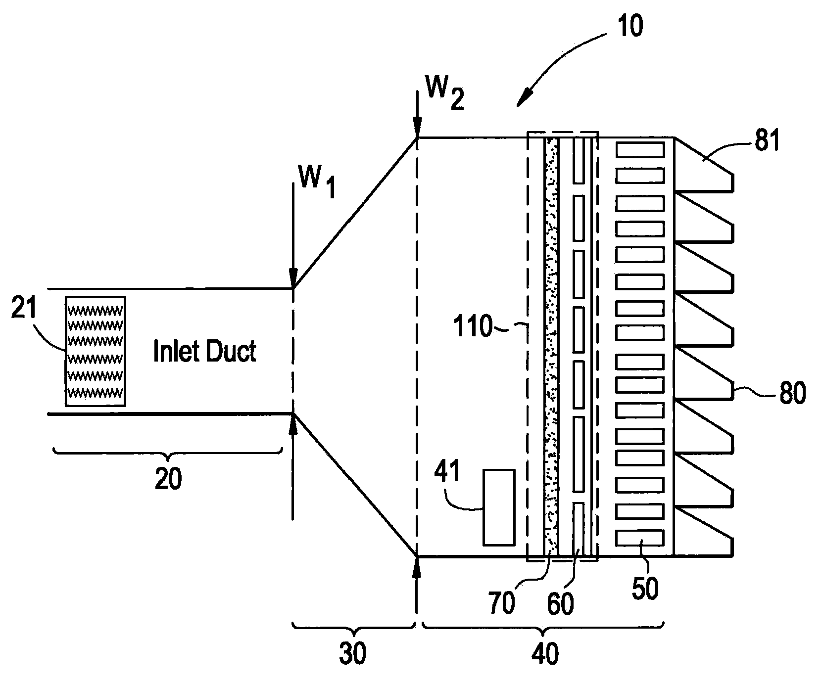
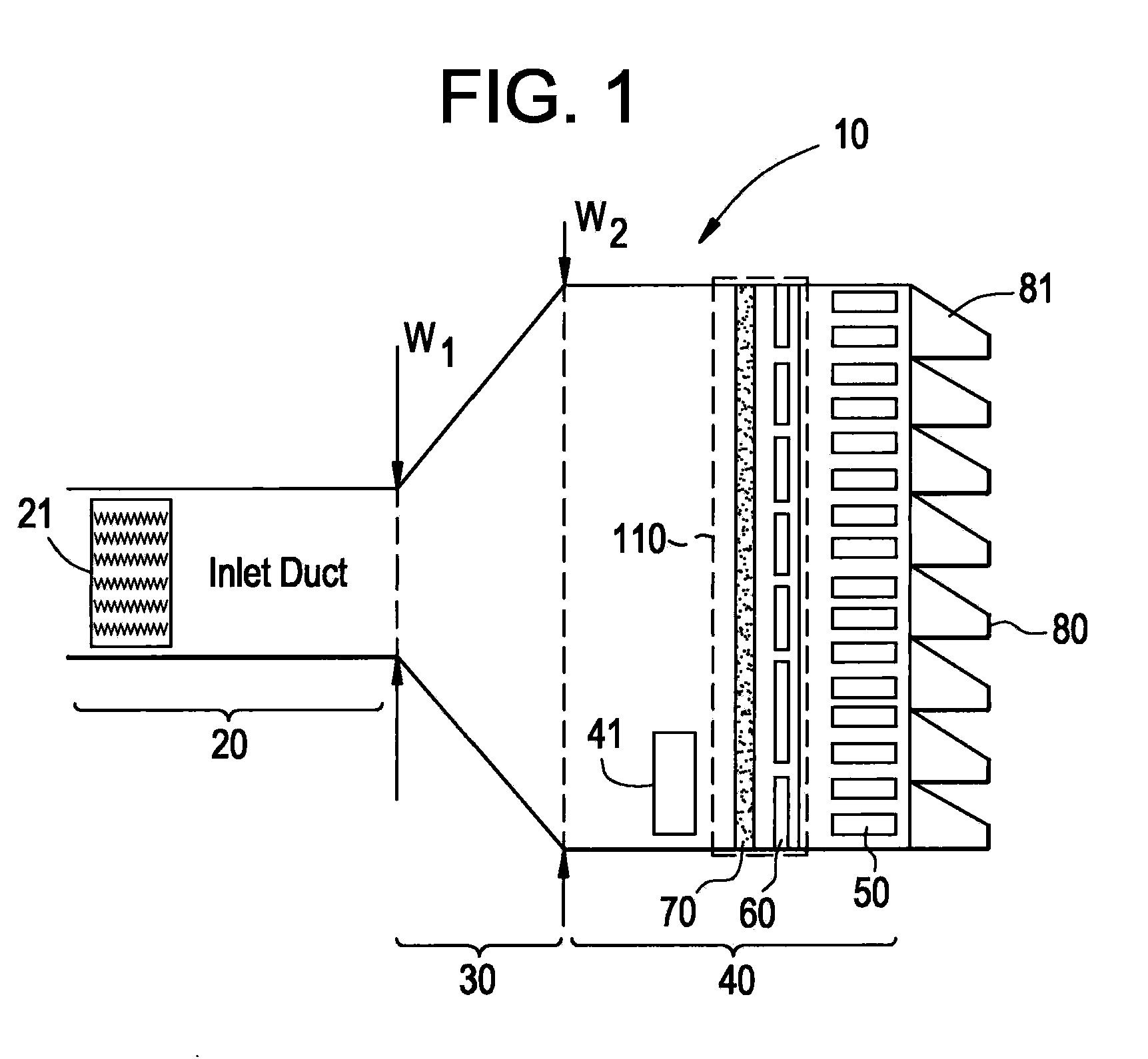
[0012]With reference to FIG. 1, a system 10 for an inlet of, e.g., a gas turbine, is provided. Here the gas turbine may have an approximate air flow range of about 50 Lb / sec to about 2000 Lb / sec in which airflow A proceeds toward the gas turbine at a range of approximate velocities of about 300 ft / min (91 meters / min) to about 3,000 ft / min (914 meters / min). The inlet includes an inlet duct 20 along which the airflow A travels toward elements of the gas turbine, such as the turbine, the compressor and the combustor, to provide for a supply of coolant and combustible air to the gas turbine which is significantly free of solid particles (i.e., dry particles) and aqueous solutions that could lead to an accumulation of corrosive deposits on those elements. A silencer section 21 is disposed within the inlet duct 20 to dampen noise generated within the gas turbine.

[0013]The inlet further includes a filter house module 40 and a transition duct 30 disposed between the inlet duct 20 and the fi...


PUM

PropertyMeasurementUnit
diametersaaaaaaaaaa
diameteraaaaaaaaaa
velocitiesaaaaaaaaaa

Abstract

A system for use with an inlet of a gas turbine through which an airflow toward the gas turbine proceeds is provided and includes a first self-cleaning stage to remove dust, snow and ice from the airflow, a second water tight stage, disposed downstream from the first stage, to prevent aerosol droplets and aqueous solutions of deliquesced particulates, which include at least portions of the dust not removed by the first stage and which are re-released into the airflow from the first stage, from proceeding along the airflow and to remove solid particulates not removed by the first stage from the airflow, and a third water removal stage, disposed downstream from the second stage, to remove from the airflow aerosol droplets leaking from the second stage.

Description

BACKGROUND[0001]Inlet air filtration systems are generally employed for use with gas turbines and operate by removing salt, dust, corrosives and water (hereinafter referred to as “corrosives”) from inlet air in order to prevent their entry into the gas turbine. Corrosives can enter the gas turbines in various forms, such as solids (i.e., dry salt) or aqueous solutions (i.e., wet salt), and corrode the gas turbine elements. This corrosion could lead to operational failures and financial losses. As such, it is typically necessary to provide for corrosion mitigation to the gas turbine engine by way of an inlet filtration system that reduces the amount of corrosives entering the gas turbine.[0002]The corrosives can exist in several states which can enter the gas turbine. One state includes Solid Particulate Corrosive elements. These include salt and oxide particles which can be removed by high efficiency filters. A second state includes Liquid, or, rather, Aqueous Corrosives elements. T...

Claims


Application Information

Patent Timeline
04 Mar 2010
Publication
US20100054919A1
IPC
F04D29/70
CPC
B01D45/08; B01D46/0024; B01D46/0031; B01D46/0068; B01D46/4236; B01D46/4263; F05D2260/96; B01D2277/20
Inventors
HINER, STEPHEN DAVID; CHILLAR, RAHUL JAIKARAN