Battery terminal unit

a terminal unit and battery technology, applied in the direction of cell components, cell component details, connections, etc., can solve the problems of restricted movement of the main body opposite to the pressing direction, and achieve the effect of preventing function, facilitating joint placement, and increasing joint strength

Inactive Publication Date: 2010-03-04
SUMITOMO WIRING SYST LTD
View PDF3 Cites 4 Cited by
  • Summary
  • Abstract
  • Description
  • Claims
  • Application Information

AI Technical Summary

Benefits of technology

[0032]The joint may extend in the pressing direction of the main body toward the bolt holding portion and may be arranged at a position adjacent to the bolt holding portion in a direction orthogonal to a longitudinal direction of the stud bolt. Thus, a space for placing the joint easily can be ensured at the position adjacent to the bolt holding portion in the direction orthogonal to the longitudinal direction of the stud bolt as compared with a position adjacent to the bolt holding portion in the longitudinal direction of the stud bolt where a part to be attached to the stud bolt or a wall surface of the battery can be present.
[0033]Two joints may be arranged at opposite sides of the bolt holding portion, and the engaging portion may be connected with both joints. With this construction, the bolt holding portion is enclosed by the main body, the two joints and the engaging portion. Thus, shaking movements of the rotation restricting member relative to the battery terminal are restricted in all directions orthogonal to the longitudinal direction of the stud bolt. Further, the engaging portion is connected with the two joints. Hence, the strength of the joints is higher and a higher detachment preventing function is displayed.
[0034]The engaging portion may be separated from the joints and connected with the joints. With this construction, assembling operability with the battery terminal is better as compared with the case where the engaging portion is made integral to one joint by a hinge. This is particularly effectively in the case where the spacing between the post fitting portion and the bolt holding portion is short. Additionally, a cost reduction can be realized.

Problems solved by technology

Furthermore, movement of the main body opposite to the pressing direction is restricted by the engagement of the detachment restricting member with the mounting member to be tightened to the stud bolt.

Method used


Image

  • Battery terminal unit
  • Battery terminal unit
  • Battery terminal unit

Examples


first embodiment

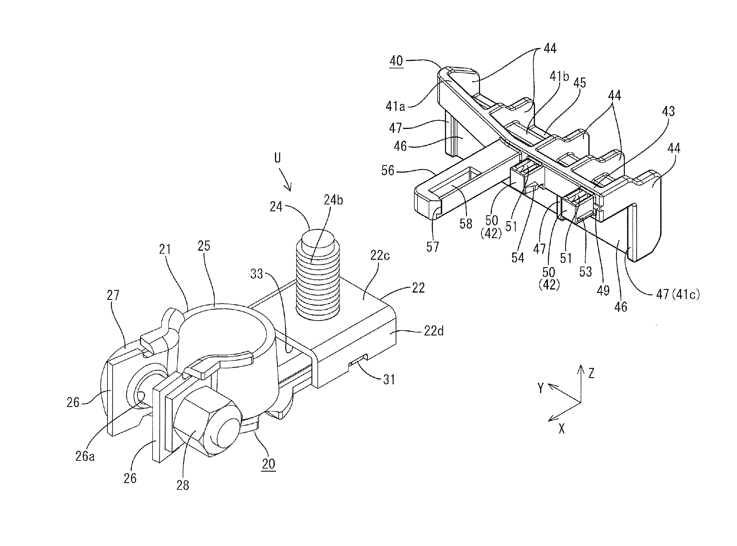
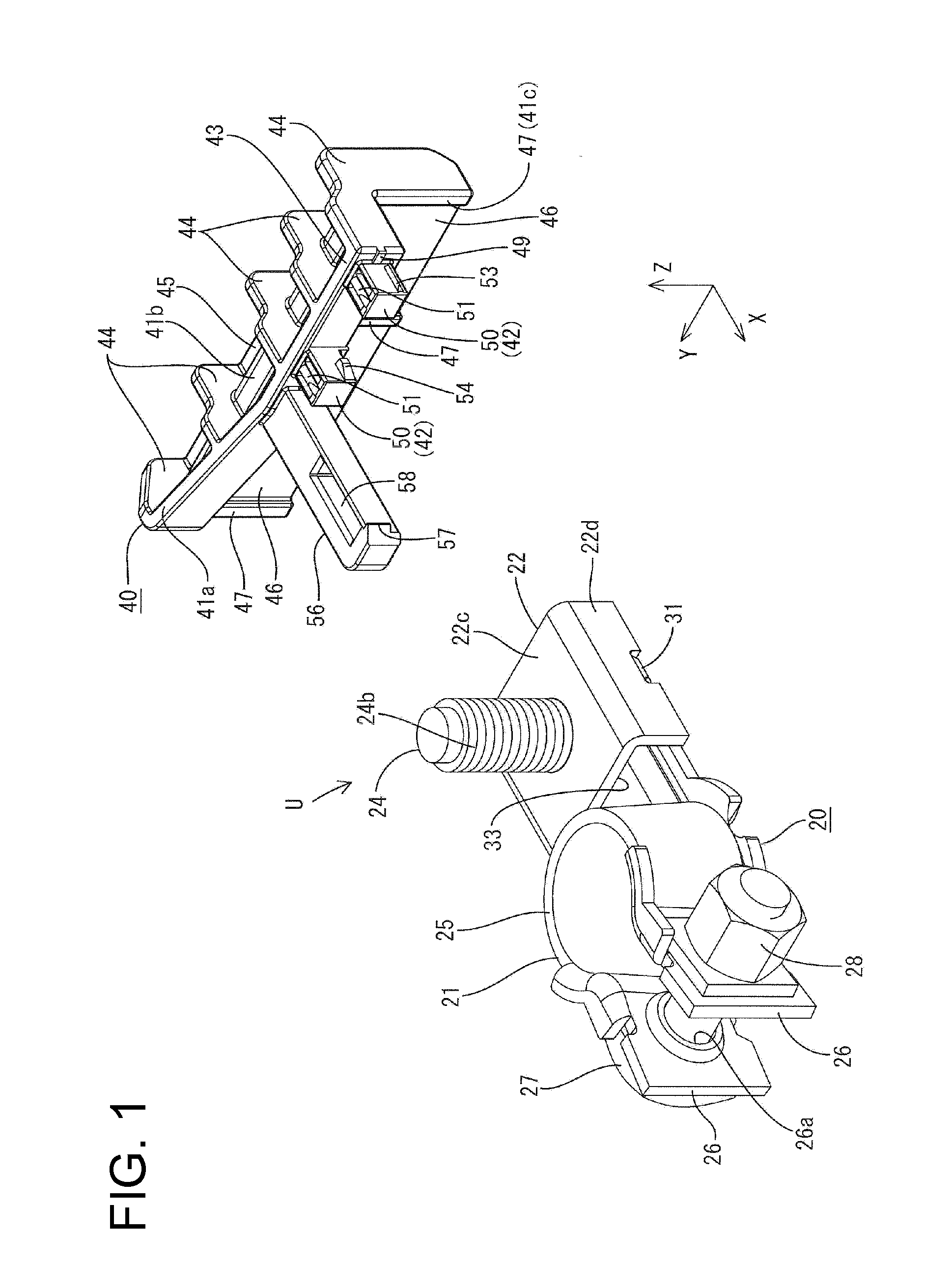
[0092]the invention is described with reference to FIGS. 1 to 20. A battery terminal unit of this embodiment is identified by the letter U and includes a battery terminal 20 to be connected with a battery 10 that may be installed in an automotive vehicle. The battery terminal unit U also has a rotation restricting member 40 to be attached to the battery terminal 20. In the following description, reference is made to FIGS. 3 to 5, 7 to 9, 11, 13, 16, 18 and 20 concerning a vertical direction. X-axis, Y-axis and Z-axis are shown in some of the drawings and graphical representations are made so that the respective axis directions are those shown in the respective drawings.

[0093]As shown in FIGS. 15 to 17, the battery 10 includes a substantially box-shaped battery main body 11 and a substantially cylindrical battery post 12 that stands on an upper surface 11a of the battery main body 11. The battery post 12 is made of lead or the like and is mounted near a corner of the upper surface 11...

fourth embodiment

[0167]Although the bracket of the current sensor is made of metal in the above fourth embodiment, it may be, for example, made of synthetic resin.

[0168]Although the terminal fitting or the bracket of the current sensor is illustrated as the “mounting member” to be mounted on the bolt holding portion in the above respective embodiments, something other than these may be used as the “mounting member”. Particularly, the electrical component to which the bracket is fixed can be changed, for example, to a pressure sensor or the like.

[0169]The press-fitting portions shown in the above respective embodiments can be suitably changed in the number, shape, size, arrangement and the like. The numbers, shapes, sizes, arrangements and the like of the respective ribs, retaining projection, bored portions of each press-fitting portion can be suitably changed.

[0170]It is also possible to omit the press-fitting portions.

[0171]A fifth preferred embodiment of the present invention is described with re...

fifth embodiment

[0213]As shown in FIGS. 55 and 56, a current sensor 80 is mounted or mountable on the bolt holding portion 22-C of the battery terminal 20-C according to this embodiment. The current sensor 80 is electrically connected to a specified (predetermined or predeterminable) electrical circuit using a battery 10-C as a power source via a connector or the like and adapted to detect a current flowing in this electrical circuit. This current sensor 80 is such that a bracket 82 is integrally or unitarily provided on a (preferably substantially block-shaped) main body 81, and this bracket 82 is to be mounted on the bolt holding portion 22-C with a stud bolt 24-C inserted through the bracket 82. The bracket 82 includes a battery mounting portion 83 to be at least partly placed on the upper surface of the bolt holding portion 22-C and formed with a bolt insertion hole 82a and a pair of anti-rotation pieces 84 projecting substantially downward from the opposite lateral edges of the battery mountin...


PUM


Abstract

A rotation restricting member (40) of a battery terminal unit (U) is provided with a main body (41) capable of restricting a mounting angle of a battery terminal (20) with respect to a battery post (12) by coming into contact with a battery (10) with the battery terminal (20) connected with the battery post (12), press-fitting portions (42) formed integral to the main body (41) and adapted to fix the rotation restricting member (40) to the battery terminal (20) by being press-fitted into an opening (32) formed in a side surface of a bolt holding portion (22), and a detachment restricting piece (56) formed integral to the main body (41) and adapted to restrict a movement of the main body (41) in a direction opposite to a pressing direction by being engaged with a terminal fitting (60) tightened to a stud bolt (24).

Description

BACKGROUND OF THE INVENTION[0001]1. Field of the Invention[0002]The invention relates to a battery terminal unit.[0003]2. Description of the Related Art[0004]Japanese Unexamined Patent Publication No. H11-135102 discloses a battery terminal to be connected with a battery post on the upper surface of a battery of an automotive vehicle or the like. This battery terminal includes a post fitting portion to be fit on the battery post for connection, a wire connecting portion to be connected with a wire and a handle connecting the post fitting portion and the wire connecting portion. An anti-rotation piece projects from the handle. The post fitting portion is fit on the battery post and a bolt of the post fitting portion is tightened. This tightening may apply a torque to the battery terminal. However, the anti-rotation piece contacts a side surface of the battery to prevent the rotation of the battery terminal.[0005]The anti-rotation piece of the battery terminal disclosed in Japanese Un...

Claims


Application Information

Patent Timeline
Patent Type & Authority Applications(United States)
IPC IPC(8): H01R4/42
CPCH01M2/206H01M2/34H01R4/305H01R2201/26H01R11/283H01R11/287H01R11/12Y02E60/10
Inventor MIZUTANI, YOSHIHIRO
Owner SUMITOMO WIRING SYST LTD
Why Eureka
Try Eureka