Housing for Hand-Held Device with Extruded Element having Area of Bulk Material and Corresponding Method

a technology of extruded elements and housings, which is applied in the direction of electrical apparatus construction details, electrical apparatus casings/cabinets/drawers, instruments, etc., can solve the problems of difficult deviation, limited range of housings, and limited type of housings that have historically been produced through such a manufacturing process

Inactive Publication Date: 2010-03-04
GOOGLE TECH HLDG LLC
View PDF31 Cites 31 Cited by
  • Summary
  • Abstract
  • Description
  • Claims
  • Application Information

AI Technical Summary

Benefits of technology

[0014]The present invention further provides a hand-held electronic device including a housing. The housing of the hand-held electronic device includes an extruded element having a profile corresponding to a cross-section of the element, which is perpendicular to the direction of extrusion. The extruded element includes within the profile, one or more areas of bulk material. The one or more areas of the bulk material include a machined surface along the length of the extruded element in the direction of the extrusion including a resulting machined profile. The resulting machined profile varies along the length of the extruded element in the direction of extrusion, while maintaining the continuity of the formed surface.
[0015]The present invention still further provides a method for forming a housing for a hand-held electronic device. The method includes extruding an element having a profile corresponding to a cross-section of the element, which is perpendicular to the direction of extrusion, where within the profile, one or more areas of bulk material are included. The bulk material included within the profile of the extruded element is then machined along the length of the extruded element, such that the resulting machined profile varies along the length of the extruded element in the direction of the extrusion, while maintaining the continuity of the formed surface.

Problems solved by technology

To date, such a construction has resulted in housings which have very limited amounts of variability along the length of the extrusion.
In some instances, it can be very difficult to deviate from such a style even when function and / or aesthetics would prefer such a deviation, which limits the type of housings that have historically been produced through such a manufacturing process.

Method used


Image

  • Housing for Hand-Held Device with Extruded Element having Area of Bulk Material and Corresponding Method
  • Housing for Hand-Held Device with Extruded Element having Area of Bulk Material and Corresponding Method
  • Housing for Hand-Held Device with Extruded Element having Area of Bulk Material and Corresponding Method

Examples


Embodiment Construction

)

[0024]While the present invention is susceptible of embodiment in various forms, there is shown in the drawings and will hereinafter be described presently preferred embodiments with the understanding that the present disclosure is to be considered an exemplification of the invention and is not intended to limit the invention to the specific embodiments illustrated.

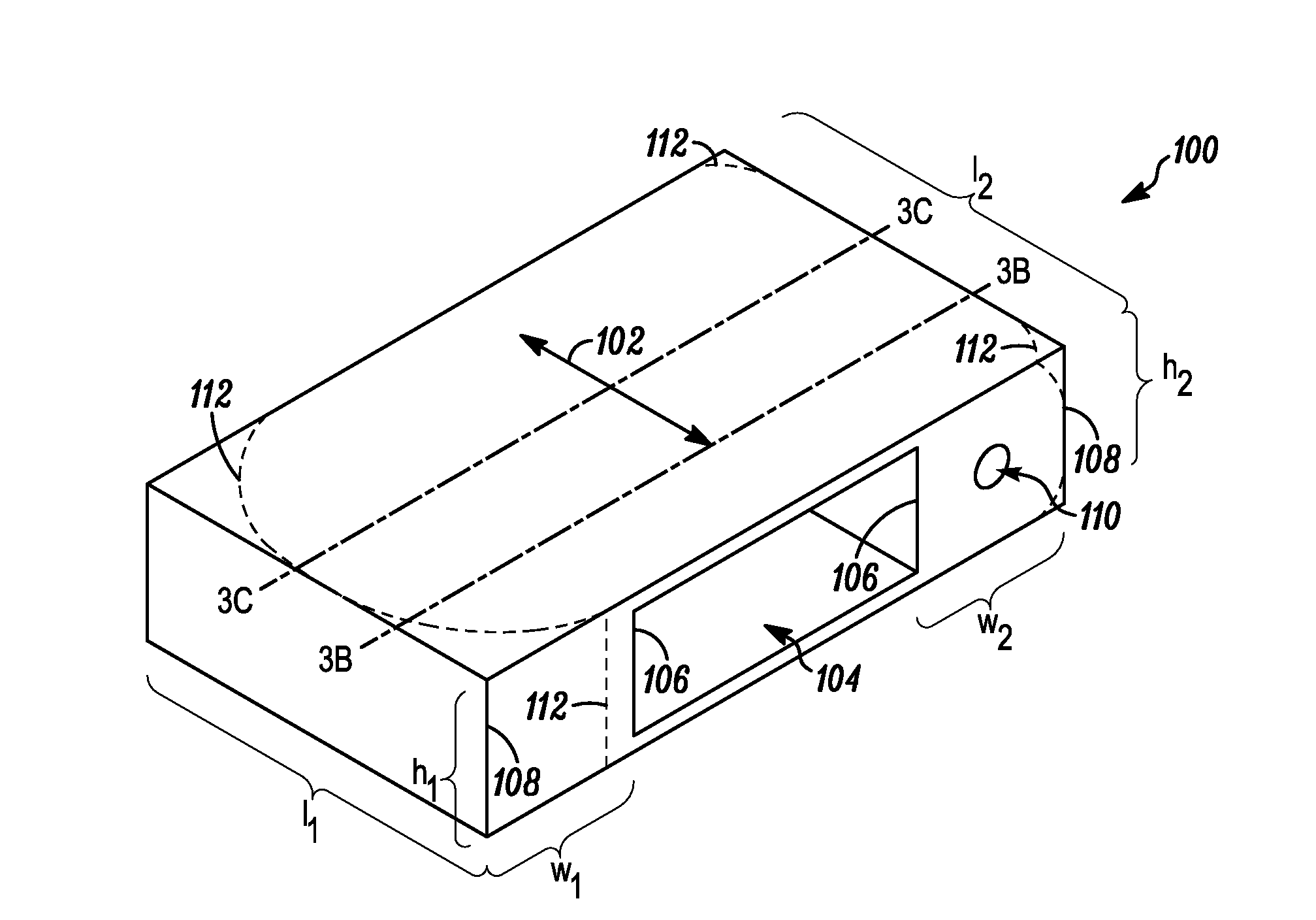
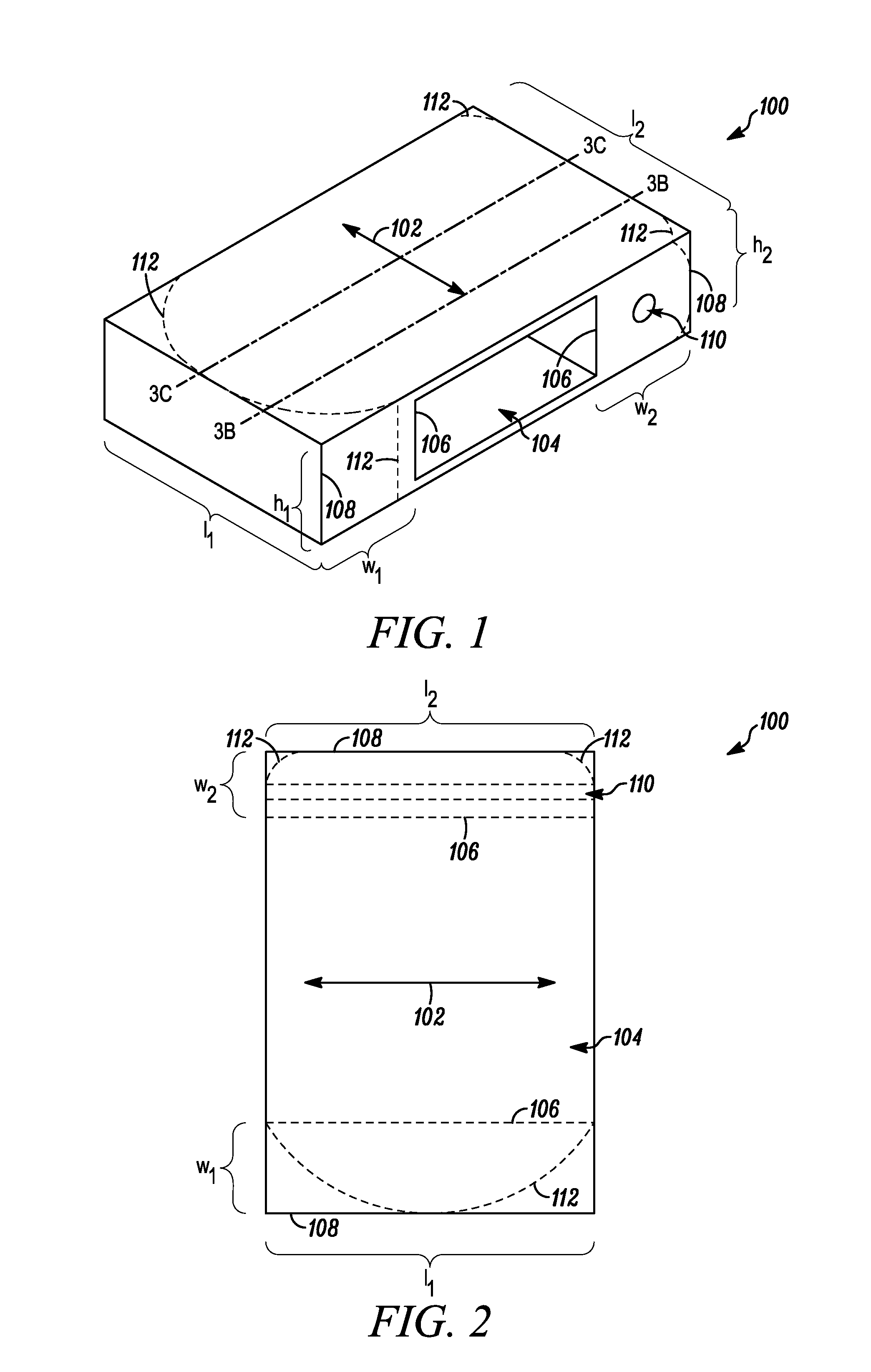
[0025]FIG. 1 illustrate a perspective view of an exemplary extruded element 100 for use as a housing for a hand-held electronic device, which has areas of bulk material to support areas of subsequent machining, in accordance with at least one aspect of the present invention. In connection with the illustrated embodiment, an arrow 102 defines a direction of extrusion. An extrusion has a profile, which is perpendicular to the direction of extrusion, that is generally uniform and defined by the size and shape of an opening in a die through which the extruded material is pushed and / or drawn. In the illustrated embodiment, th...


PUM

PropertyMeasurementUnit
lengthaaaaaaaaaa
areaaaaaaaaaaa
sizesaaaaaaaaaa

Abstract

A housing for a hand-held electronic device and a corresponding method for forming the same are provided. The housing includes an extruded element having a profile corresponding to a cross-section of the element, which is perpendicular to the direction of extrusion, where the extruded element includes within the profile, one or more areas of bulk material. The one or more areas of the bulk material include a machined surface along the length of the extruded element in the direction of the extrusion including a resulting machined profile. The resulting machined profile varies along the length of the extruded element in the direction of extrusion, while maintaining the continuity of the formed surface.

Description

CROSS REFERENCE TO RELATED APPLICATIONS[0001]This application claims priority from a U.S. Provisional Patent Application Ser. No. 61 / 093,320, filed Aug. 30, 2008.FIELD OF THE INVENTION[0002]The present invention relates generally to a housing for a hand-held electronic device and a method for forming the same, and more particularly, to a housing having an extruded element including a profile with one or more machinable areas.BACKGROUND OF THE INVENTION[0003]Hand-held electronic devices have often been made from two separately formed halves of a housing, a front half and a back half, which are coupled together with one or more fasteners, within which the electrical and mechanical components forming the device are placed. Often times, each of the front half and the back half are formed from plastic or other material using an injection molding process, which enables considerable freedom in incorporating diverse sizes and shapes, and which can be used to produce various functional and / o...

Claims


Application Information

Patent Timeline
Patent Type & Authority Applications(United States)
IPC IPC(8): H05K7/00H04M1/00H01S4/00
CPCB21C23/14B21C23/142Y10T29/49002B21C35/026B21C35/02B21C35/023
Inventor WEISS, GARY R.ALLORE, JOSEPH L.WOJACK, JASON P.
Owner GOOGLE TECH HLDG LLC
Why Eureka
Try Eureka