Tourniquet assembly

a technology of windlass straps and tourniquets, which is applied in the field of windlass strap assemblies, can solve the problems of increasing the weight and bulk of the already substantial gear, affecting the safety of the patient, so as to reduce the amount of main tourniquet strap bunching, the effect of shortening the length of the windlass strap

Active Publication Date: 2010-03-04
KIRKHAM JEFFREY B
View PDF6 Cites 74 Cited by
  • Summary
  • Abstract
  • Description
  • Claims
  • Application Information

AI Technical Summary

Benefits of technology

[0004]Anchor means for anchoring the attachment means in a position for applying the tourniquet may be disposed on a back surface of the main strap opposite the main strap's front surface. One example of anchor means is an anchor strap including a plurality of loops formed by attaching (e.g., stitching) the anchor strap to the main strap at a plurality of locations along the length of the anchor strap. The assembly also includes an elongate windlass crank that is attachable to the windlass strap during use so that when the crank is rotated the windlass strap is twiste

Problems solved by technology

However, tourniquets are typically carried as a separate piece of gear, adding additional weight and bulk to the already substantial gear that a soldier or emergency services person must carry on his or her person.
Further, depending on how/when a tourniquet is carried, access to and/or efficient use of the tourniquet can be difficult.
These difficulties can be compounded when an injured person attempts

Method used


Image

  • Tourniquet assembly
  • Tourniquet assembly
  • Tourniquet assembly

Examples


Embodiment Construction

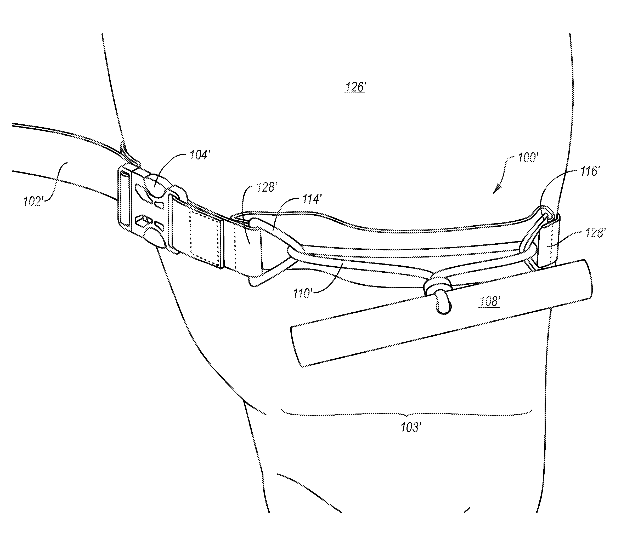
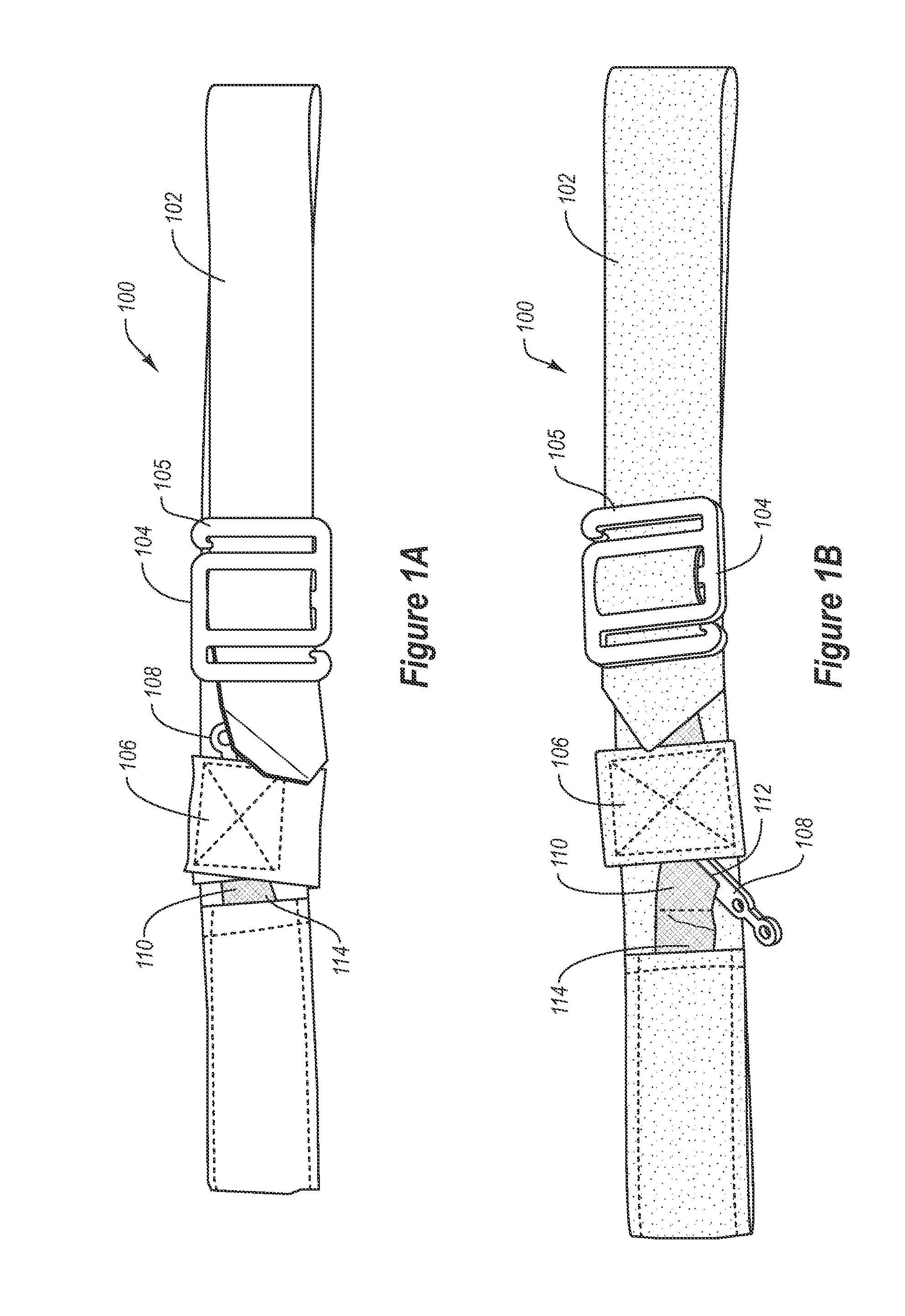
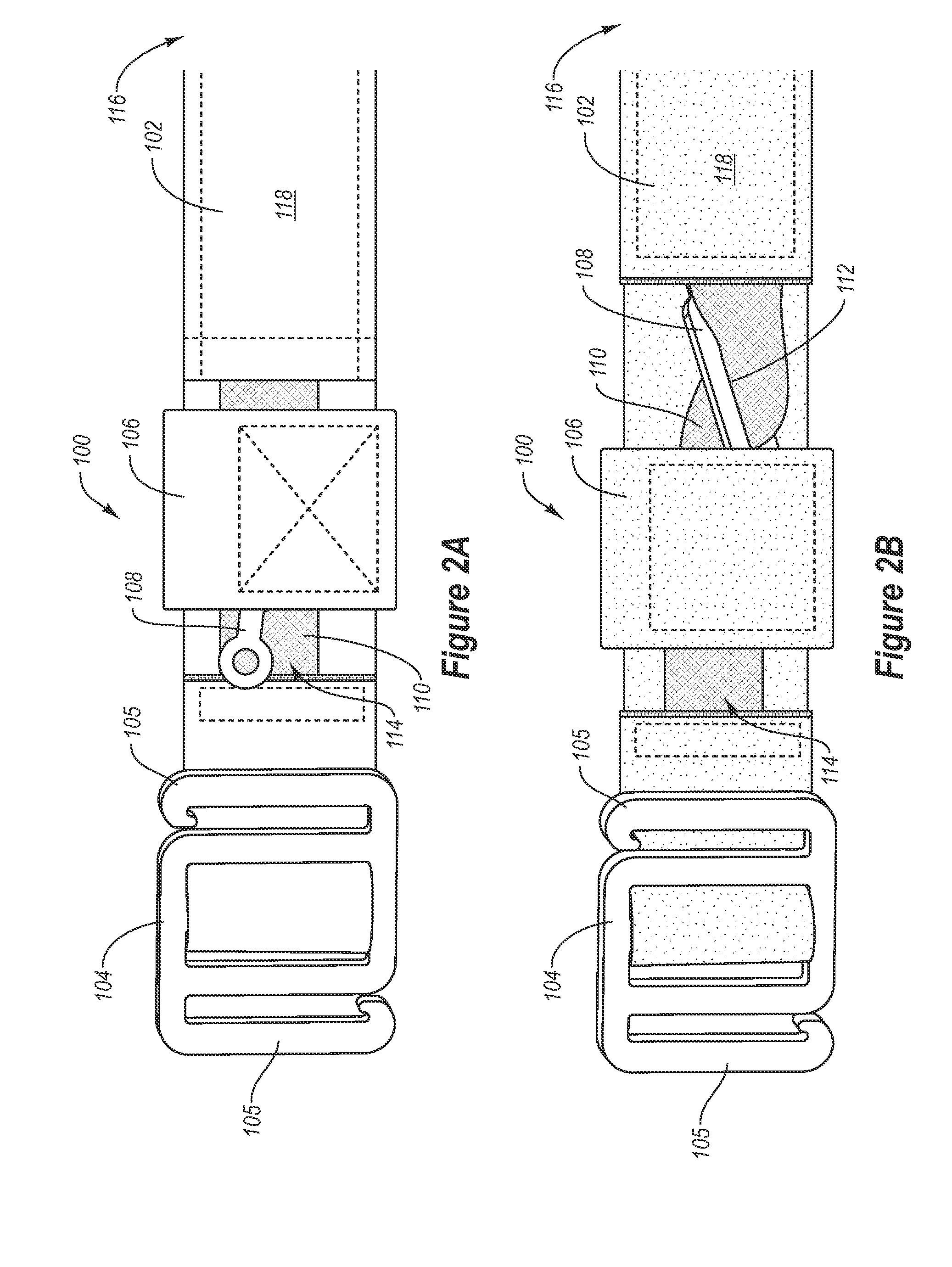
[0003]The present invention is directed to windlass tourniquet assemblies that are integrated into belts, harnesses, straps, slings (such as rifle slings), or other similar objects. The present invention also includes methods for applying the integrated tourniquets and assemblies. For example, in one embodiment, a windlass tourniquet assembly includes an elongate main strap extending between a first end and an opposite second end, and attachment means (e.g., a buckle) for attaching the first end of the main strap to the second end of the strap. At least a portion of the attachment means is disposed at the first end of the elongate main strap. The assembly further includes a windlass strap extending between a first and second end, the first end of the windlass strap being secured to a front surface of the main strap at the first end of the main strap near the buckle or other attachment means. The second end of the windlass strap is secured to the main strap at a location a predetermi...


PUM


Abstract

A tourniquet assembly including an elongate main strap, attachment means for attaching the first end of the main strap to the second end of the main strap, a windlass strap including a first end secured to the front of the main strap near the attachment means and a second end secured to the main strap a predetermined distance away from the attachment means, an elongate windlass crank attachable to the windlass strap during use so that as the crank is rotated the windlass strap twists, effectively shortening the length of the windlass strap and tightening the main strap for use as a tourniquet during use. anchor means for anchoring the attachment means in a position for applying the tourniquet may be disposed on the back side of the main strap.

Description

CROSS-REFERENCE TO RELATED APPLICATIONS[0001]This application claims the benefit of U.S. Provisional Patent Application 61 / 190,964 filed Sep. 4, 2008, titled “INTEGRATED WINDLASS TOUNIQUETS”, and United States Provisional Patent Application 61 / 197,084 filed Oct. 23, 2008, titled “WINDLASS PULLEY TOUNIQUET SLING”. Both of the foregoing applications are incorporated by reference in their entirety.BACKGROUND OF THE INVENTIONThe Relevant Technology[0002]Various types of tourniquets have been used when necessary to stop the flow of blood through an injured arm or leg so as to prevent death of the injured through loss of blood. However, tourniquets are typically carried as a separate piece of gear, adding additional weight and bulk to the already substantial gear that a soldier or emergency services person must carry on his or her person. Further, depending on how / when a tourniquet is carried, access to and / or efficient use of the tourniquet can be difficult. These difficulties can be com...

Claims


Application Information

Patent Timeline
IPC IPC(8): A61B17/132
CPCA61B17/1322
Inventor KIRKHAM, JEFFREY B.
Owner KIRKHAM JEFFREY B
Why Eureka
Try Eureka