Modular bone fixation device for treatment of fractures and related methods

a bone fixation device and module technology, applied in the field of surgical implants, can solve the problems of lack of cost effectiveness, affecting the treatment effect of affected bones, and difficulty in achieving the effect of cost effectiv

Active Publication Date: 2010-03-04
UPEX HLDG
View PDF41 Cites 20 Cited by
  • Summary
  • Abstract
  • Description
  • Claims
  • Application Information

AI Technical Summary

Benefits of technology

[0012]This and other objects, features, and advantages in accordance with the present invention are provided by a bone fixation device comprising a primary bone plate. The primary bone plate may include an elongate member having at least one first fastener-receiving passageway therein to receive at least one first fastener to anchor the primary bone plate to a long bone of a patient, and an enlarged head member extending from the elongate member and having at least one secondary bone plate-receiving passageway therein. The bone fixation device may also include at least one secondary bone plate received in the secondary bone plate-receiving passageway and having at least one second fastener-receiving passageway therein to receive at least one second fastener to anchor the secondary bone plate to fractured end portions of the long bone of the patient. Advantageously, the bone fixation device may be used in anatomically diverse patient applications while being cost effective.

Problems solved by technology

When the human body is subjected to high force impact or stress, the effected bones may fracture.
At other times, bones may heal in positions that are mechanically or functionally disadvantageous for normal or optimal functioning (malunions).
Potential drawbacks to the disclosed bone plates are: a lack of cost effectiveness, complexity of implantation, and limitations of the bone plate to engage certain fragments because of the predetermined morphology of the manufactured plate.
This may be problematic for cost sensitive environments, for example, in ambulatory surgery centers (ASC) and other outpatient health care facilities in the United States and abroad.

Method used


Image

  • Modular bone fixation device for treatment of fractures and related methods
  • Modular bone fixation device for treatment of fractures and related methods
  • Modular bone fixation device for treatment of fractures and related methods

Examples


Embodiment Construction

[0027]The present invention will now be described more fully hereinafter with reference to the accompanying drawings, in which preferred embodiments of the invention are shown. This invention may, however, be embodied in many different forms and should not be construed as limited to the embodiments set forth herein. Rather, these embodiments are provided so that this disclosure will be thorough and complete, and will fully convey the scope of the invention to those skilled in the art. Like numbers refer to like elements throughout.

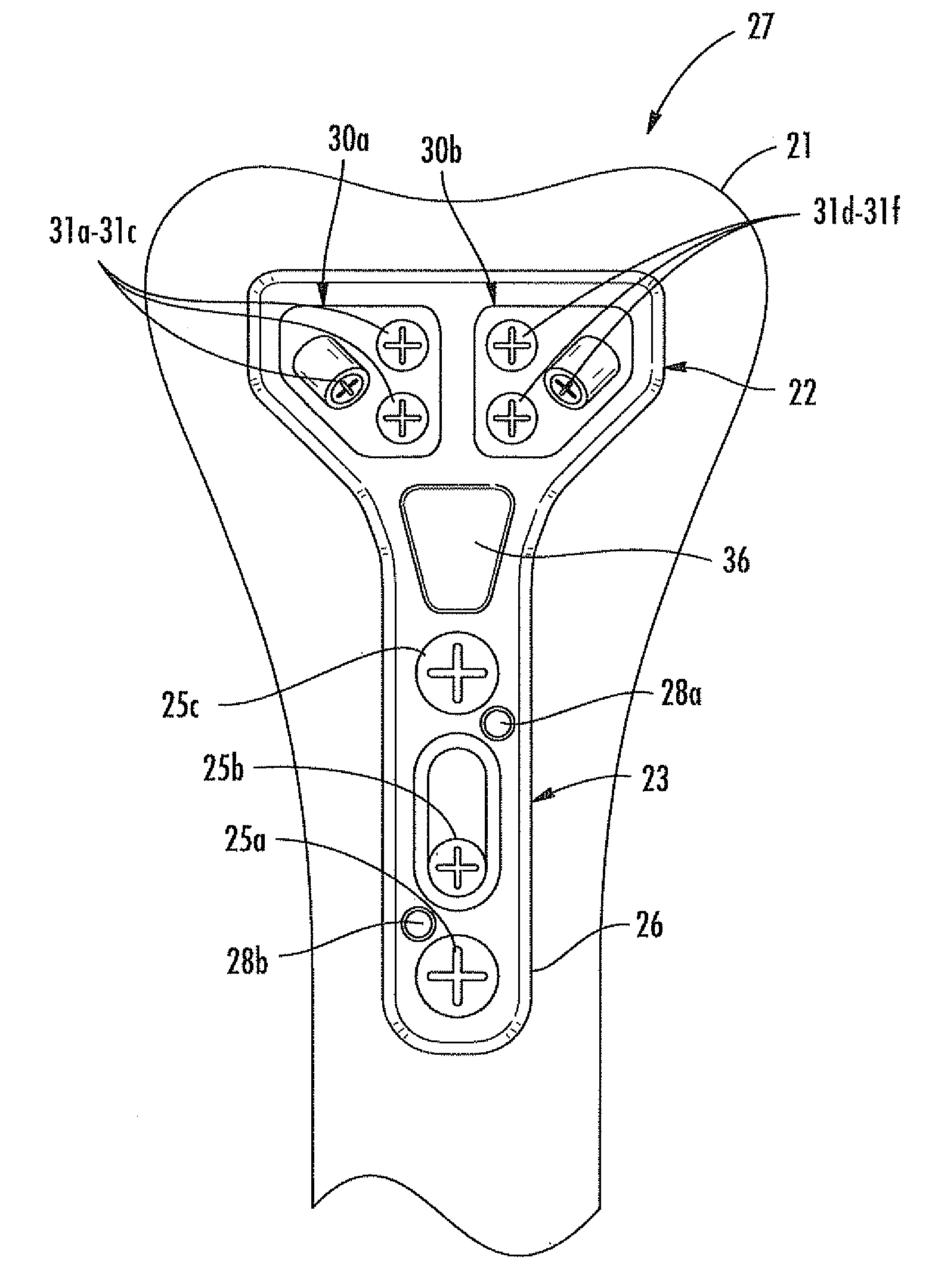
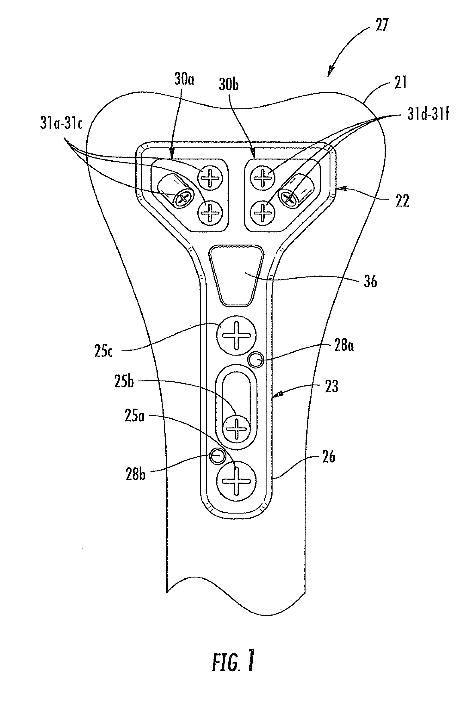
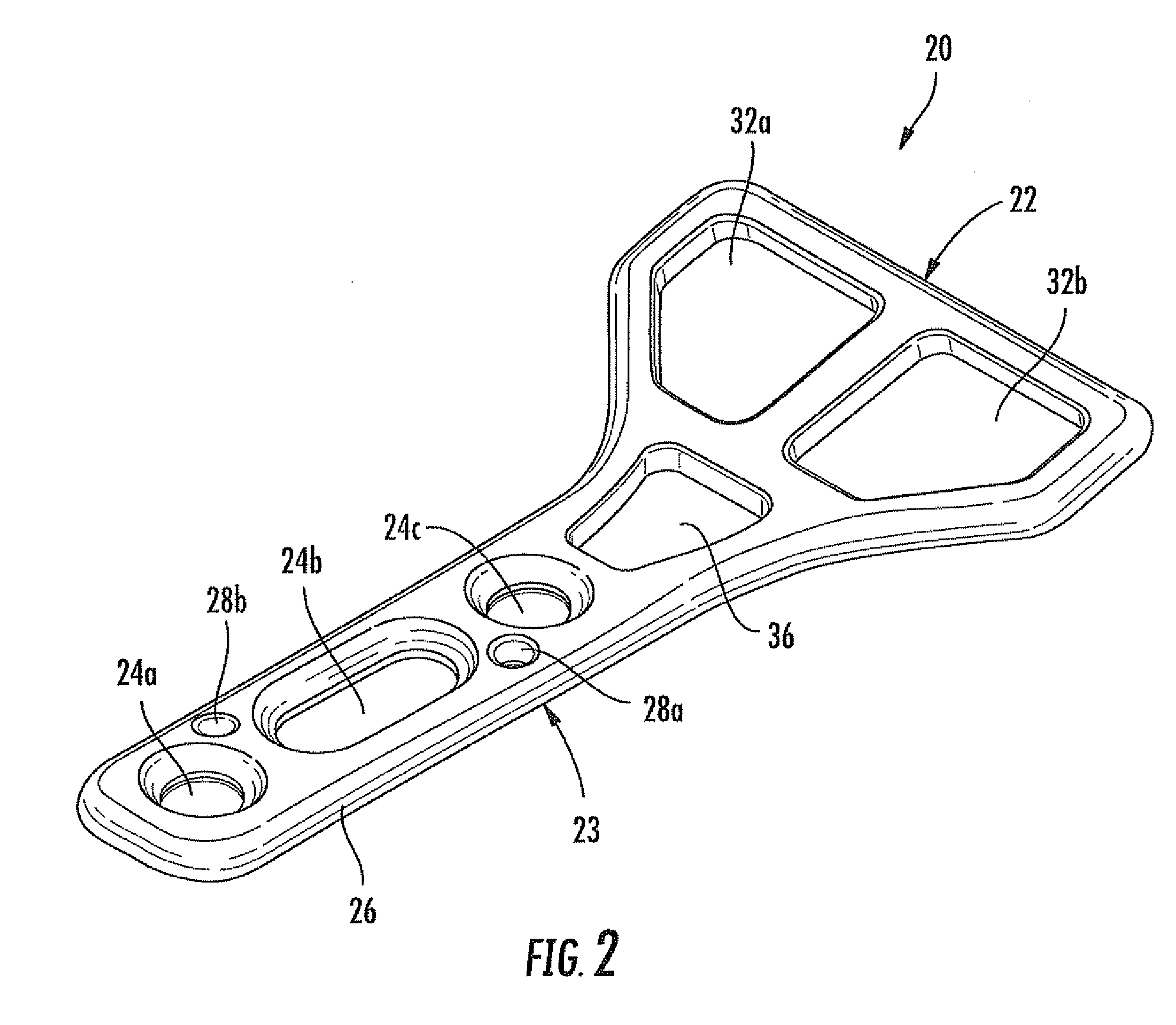
[0028]Referring initially to FIGS. 1-6, a bone fixation device 27 is now described. As will be appreciated by those skilled in the art, the bone fixation device 27 may be used in bone fixation treatments, i.e. open reduction internal fixation (ORIF). The bone fixation device 27 may be used to treat a fractured long bone, for example, the illustrated radius bone 21 (FIG. 1), in a patient, more particularly, a distal juxta-articular radius bone fracture.

[002...


PUM


Abstract

A bone fixation device may include a primary bone plate. The primary bone plate may include an elongate member having a first fastener-receiving passageway therein to receive a first fastener to anchor the primary bone plate to a long bone of a patient, and an enlarged head member extending from the elongate member and having a secondary bone plate-receiving passageway therein. The bone fixation device may also include a secondary bone plate received in the secondary bone plate-receiving passageway and having a second fastener-receiving passageway therein to receive a second fastener to anchor the secondary bone plate to fractured end portions of the long bone of the patient.

Description

FIELD OF THE INVENTION[0001]The present invention relates to the field of surgical implants, and, more particularly, to a bone fixation device for a peri-articular or juxta-articular region of a long bone and related methods.BACKGROUND OF THE INVENTION[0002]Within the human body, bones are the solid organs that function to move, support, and protect other soft tissue organs in the body. When the human body is subjected to high force impact or stress, the effected bones may fracture. Sometimes, bones may even fracture under less demanding Instances due to certain medical conditions (pathologic fractures), for example, Osteoporosis and Osteogenesis Imperfecta, weakening the bone system.[0003]At other times, bones may heal in positions that are mechanically or functionally disadvantageous for normal or optimal functioning (malunions). In these situations, reconstructive surgery, during which bones are cut or “rebroken,” may be necessary to restore comfort and improve function.[0004]Fra...

Claims


Application Information

Patent Timeline
Patent Type & Authority Applications(United States)
IPC IPC(8): A61B17/70
CPCA61B17/8047
Inventor GRAHAM, THOMAS JAMESFOCHT, LOUISE M.
Owner UPEX HLDG
Why Eureka
Try Eureka