
Thermal processing apparatus, thermal processing method, and storage medium

a technology of thermal processing apparatus and storage medium, applied in the direction of electric digital data processing, instruments, computing, etc., can solve the problem of serious deformation degr

Active Publication Date: 2010-03-04
TOKYO ELECTRON LTD
View PDF9 Cites 7 Cited by
  • Summary
  • Abstract
  • Description
  • Claims
  • Application Information

AI Technical Summary

Benefits of technology

[0010]The present invention has been made in view of the above circumstances. The object of the present invention is to provide a technique for preventing, when substrates are delivered by a substrate transfer means to and from a substrate holder capable of holding a plurality of substrates in a tier-like manner, a contact between a holding arm and a substrate and a contact between the holding arm and the substrate holder.
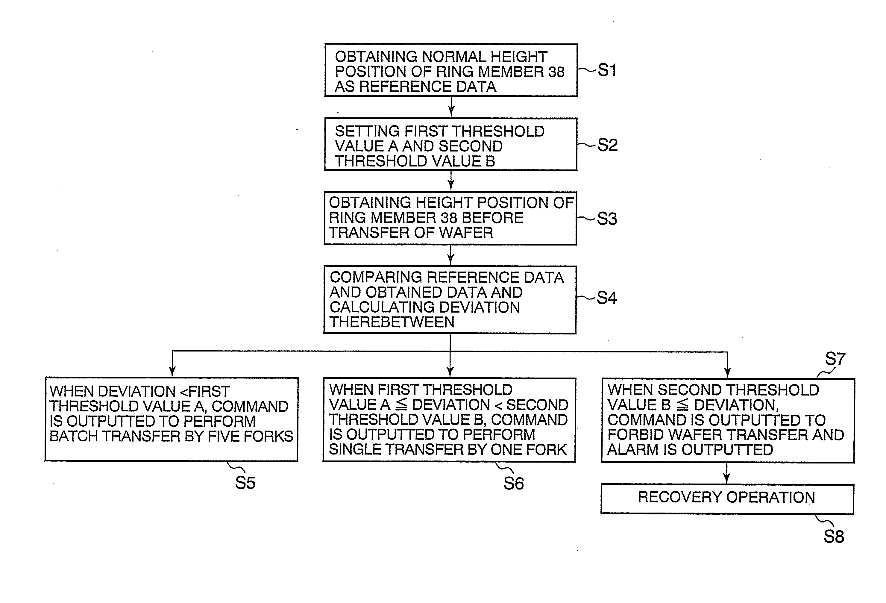
[0023]According to the present invention, at the time of the operation of the vertical thermal processing apparatus, a difference between the height position of the specific portion of the substrate holder, the specific portion having a specific relationship with respect to the substrate, and the normal height position of the specific portion is calculated. By comparing the difference and the threshold value, whether to deliver the substrate by the substrate transfer means to the substrate holder is performed or not is judged. When it is judged that the transfer operation of the substrate can not be performed, the transfer operation of the substrate by the substrate transfer means is forbidden. Thus, when the substrate is transferred to the substrate holder by the holding arm disposed on the substrate transfer means, a contact between the holding arm and the substrate and a contact between the holding arm and the substrate holder can be prevented.

Problems solved by technology

As the number of the process increases, the degree of the deformation becomes serious because of these reasons.
However, this technique is a countermeasure taken when the driving of the transfer mechanism become abnormal, and is not a countermeasure when the substrate holder becomes abnormal.

Method used


Image

  • Thermal processing apparatus, thermal processing method, and storage medium
  • Thermal processing apparatus, thermal processing method, and storage medium
  • Thermal processing apparatus, thermal processing method, and storage medium

Examples


Embodiment Construction

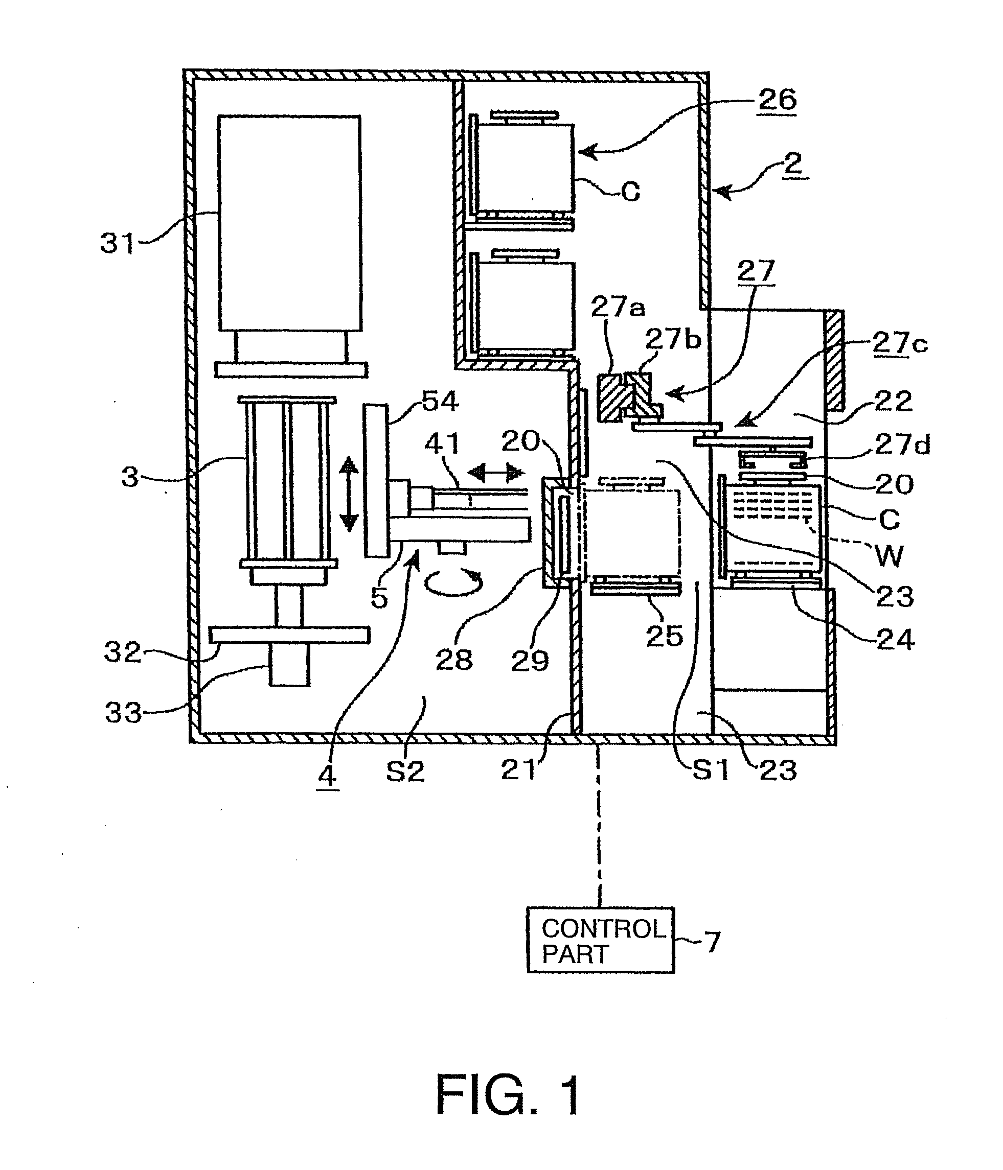
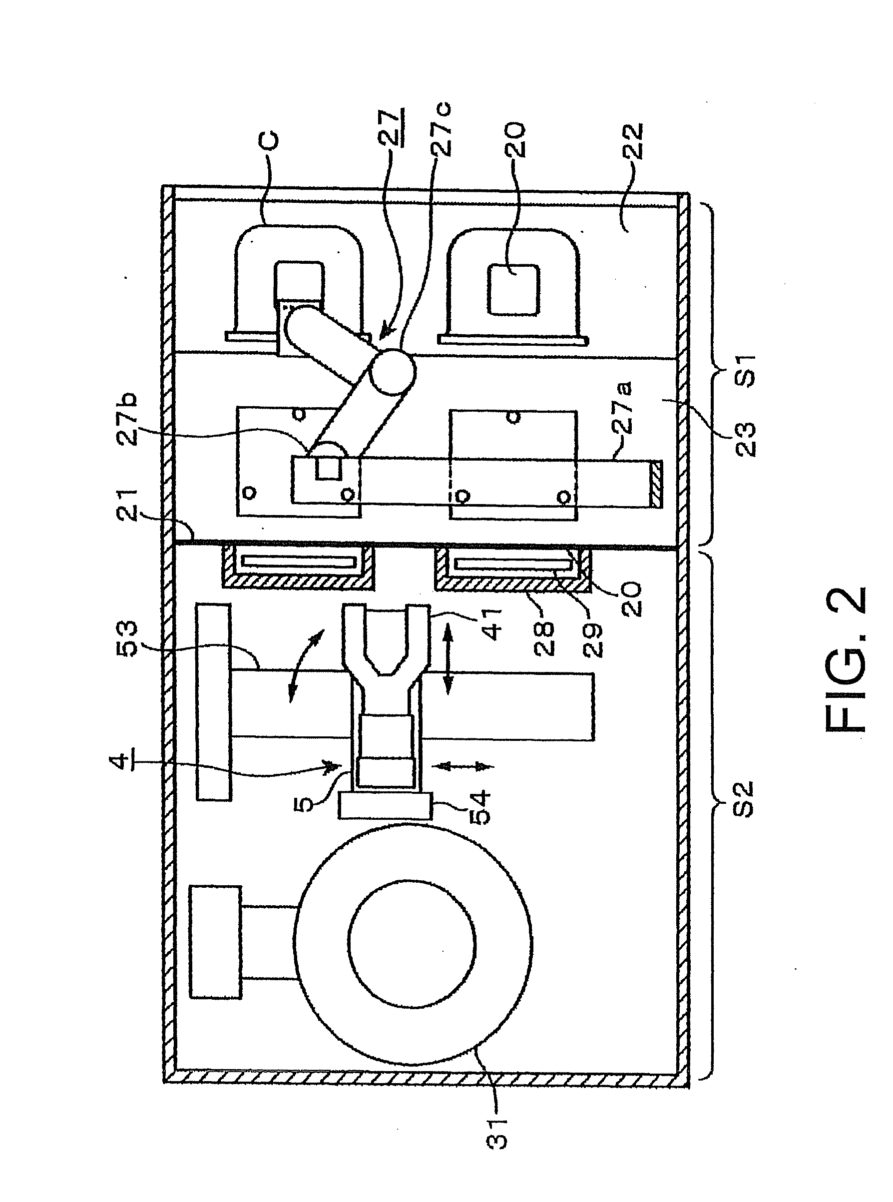
[0036]An embodiment of a vertical thermal processing apparatus of the present invention is described herebelow. FIG. 1 is a longitudinal sectional view showing an inside of the vertical thermal processing apparatus, and FIG. 2 is a schematic plan view thereof. In the drawings, the reference number 2 depicts a housing defining an external body of the apparatus. In the housing 2, there are disposed a charge / discharge area S1 through which a carrier C serving as a container containing wafers W as substrates, is carried into the apparatus and carried out therefrom, and a loading area S2 as a transport area (transfer area) through which the wafers in the carrier C are transferred and loaded into the below-described thermal processing furnace. The charge / discharge area S1 and the loading area S2 are separated from each other by a partition wall 21. The charge / discharge area S1 is filled with an atmospheric air, and the loading area S2 is filled with an inert gas atmosphere, such as nitrog...


PUM


Abstract

When a substrate is transferred by a holding arm to a multiple tier wafer boat, contact between the holding arm and the substrate is prevented. When the wafer boat is not subjected to a thermal effect, a normal height position of a ring member is obtained by relatively elevating and lowering a transfer base member with respect to the wafer boat. Before a wafer, which is not yet thermally processed, is transferred to the wafer boat, a height position of the corresponding ring member is obtained. By comparing a difference between the normal height position of the ring member and the height position of the ring member before the wafer is transported, with a threshold value, whether to transfer the wafer by the wafer transfer mechanism to the wafer boat can be judged.

Description

CROSS REFERENCE TO RELATED APPLICATIONS[0001]This application is based upon and claims the benefit of priority from the prior Japanese Patent Application No. 2008-222708 filed on Aug. 29, 2008, the entire contents of which are incorporated herein by reference.FIELD OF THE INVENTION[0002]The present invention relates to a technique for delivering substrates such as semiconductor wafers by a substrate transfer means to and from a substrate holder, in a vertical thermal processing apparatus that thermally processes substrates held by the substrate holder in a tier-like manner.BACKGROUND ART[0003]One of semiconductor manufacturing apparatuses, there is a vertical thermal processing apparatus that thermally processes a number of semiconductor wafers (hereinafter referred to as “wafers”) in block (batch). As shown in FIG. 11, for example, the vertical thermal processing apparatus includes a charge / discharge area through which a carrier, not shown, accommodating a plurality of wafers is ca...

Claims


Application Information

Patent Timeline
Patent Type & Authority Applications(United States)
IPC IPC(8): H01L21/68
CPCH01L21/67109H01L21/67098H01L21/67781H01L21/67766H01L21/324
Inventor ABE, YOTAKAHASHI, KIICHISATO, JUNYAMOTODATE, YOSHINOBU
Owner TOKYO ELECTRON LTD
Learn More